OpenMUC User Guide
![]() Download PDF Version
Download PDF Version
1. Intro
OpenMUC is a software framework based on Java and OSGi that simplifies the development of customized monitoring, logging and control systems. It can be used as a basis to flexibly implement anything from simple data loggers to complex SCADA systems. The main goal of OpenMUC is to shield the application developer of monitoring and control applications from the details of the communication protocol and data logging technologies. Third parties are encouraged to create their own customized systems based on OpenMUC. OpenMUC is licensed under the GPL. If you need an individual license please contact us.
For a short overview of OpenMUC’s goals and features please visit our overview page. This guide is a detailed documentation on how OpenMUC works and how to use it.
2. Quick Start
This chapter will give you an idea of how OpenMUC works by showing you how to run and adjust the demo framework which is part of the OpenMUC distribution.
2.1. Install OpenMUC
To install OpenMUC just download the latest version and unpack it to your favorite destination.
OpenMUC requires Java 8 or higher, therefore make sure it is installed on your machine.
2.2. Start the Demo
The OpenMUC demo contains a simple application which demonstrates how you can access channels and their records from an application. The application reads data from channels of the CSV driver, calculates new values from them and writes them to other channels. The application can be used as starting point to create your own OpenMUC application.
Open a terminal and navigate to the framework folder (<your-path>/openmuc/framework)
To start OpenMUC on Linux run:
./bin/openmuc start -fg
To start OpenMUC on Windows run:
bin\openmuc.bat
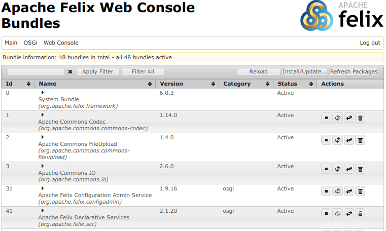
This will start the Apache Felix OSGi framework which in turn starts all the bundles located in the “bundle” folder. After initialization of the OSGi framework you should be able to see the output of the demo application.
...
17:33:00.011 INFO SimpleDemoApp - home1: current grid power = -4.672 kW
17:33:05.006 INFO SimpleDemoApp - home1: current grid power = -4.666 kW
17:33:10.007 INFO SimpleDemoApp - home1: current grid power = -4.671 kW
...
Among the bundles that are started is the Apache Gogo shell. This shell is entered once you run OpenMUC. Now type lb to list all installed bundles.
START LEVEL 1
   ID|State      |Level|Name
    0|Active     |    0|System Bundle
    ...
    7|Active     |    1|Logback Core Module
    8|Active     |    1|OpenMUC App - Simple Demo
    9|Active     |    1|OpenMUC Core - API
   10|Active     |    1|OpenMUC Core - Data Manager
   11|Active     |    1|OpenMUC Core - SPI
   12|Active     |    1|OpenMUC Data Logger - ASCII
   13|Active     |    1|OpenMUC Data Logger - SlotsDB
   14|Active     |    1|OpenMUC Driver - CSV
   15|Active     |    1|OpenMUC Server - RESTful Web Service
   16|Active     |    1|OpenMUC WebUI - Base
   17|Active     |    1|OpenMUC WebUI - Channel Access Tool
   ...
You can stop and exit the OSGi framework any time by typing ctrl+d or stop 0. For more information about the start script see chapter OpenMUC Start Script.
2.3. WebUI Walk Through
This section leads you through the framework’s WebUI.
Open a browser (works currently best with Google Chrome) and enter the URL “http://localhost:8888”. This leads you to the login page. The default user is admin and the default password is admin as well.
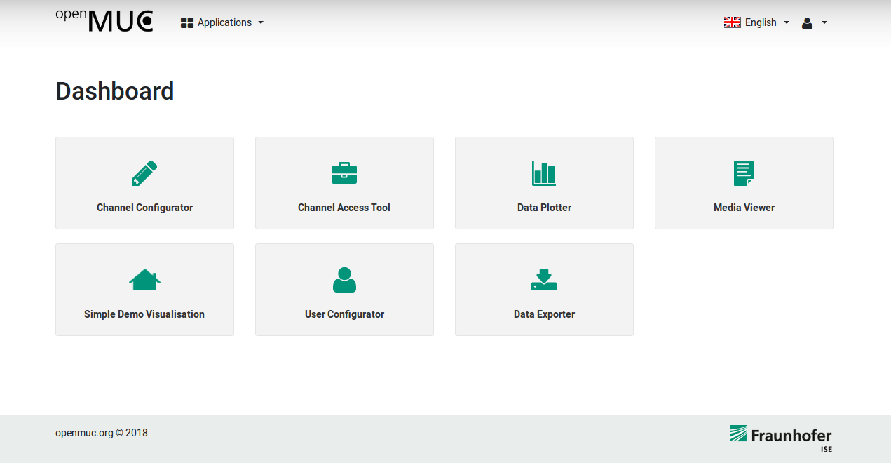
After successful login the OpenMUC Dashboard opens, which provides various plugins for configuration and visualization. A full description of the plugins can be found in the chapter Web UI.
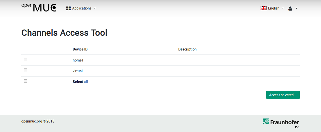
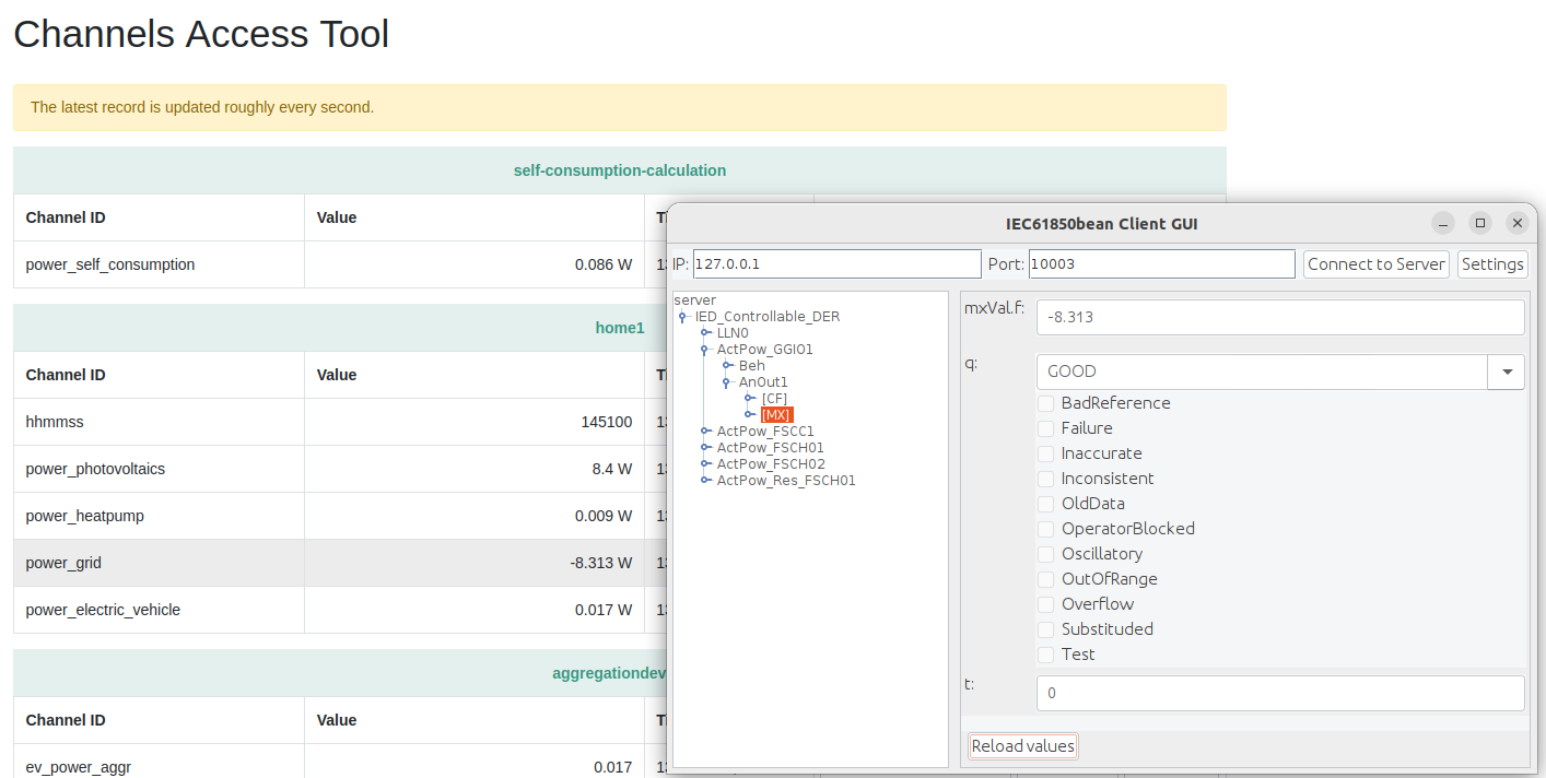
Let us first look at the Channel Access Tool which provides the current value of each channel and also enables you to write values. Click on Channel Access Tool to open this plugin. The next page lists all available devices which are currently configured in OpenMUC. Select the home1 and proceed with Access selected.
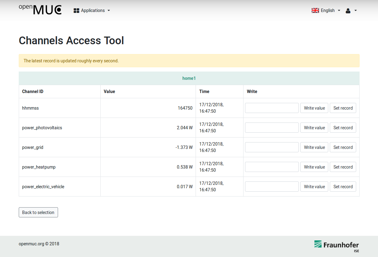
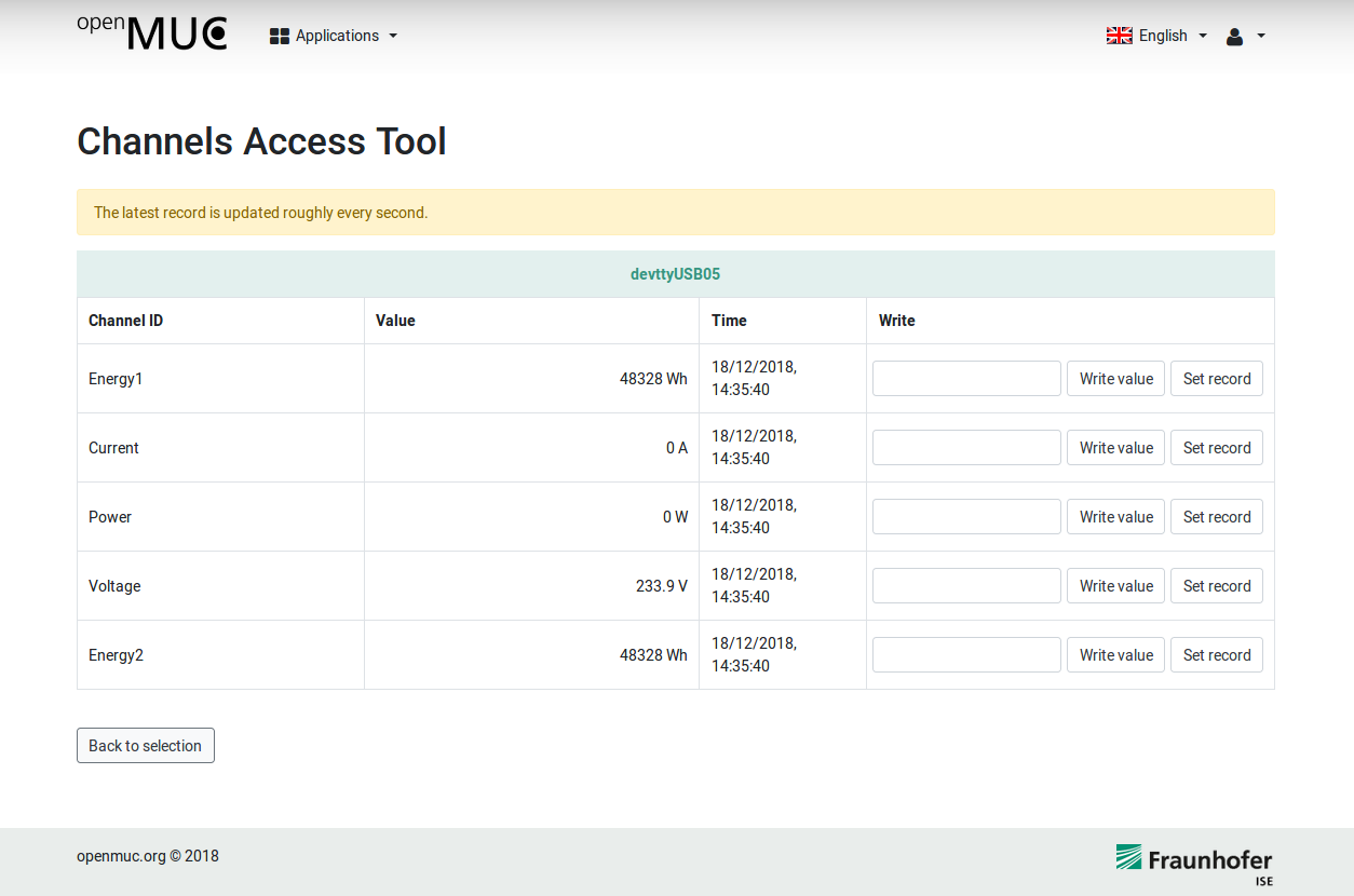
On the next page you will see the latest records of all channels of home1. Each record consists of a data value, a timestamp when it was sampled and a quality flag.
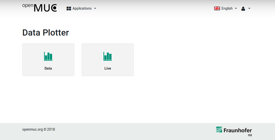
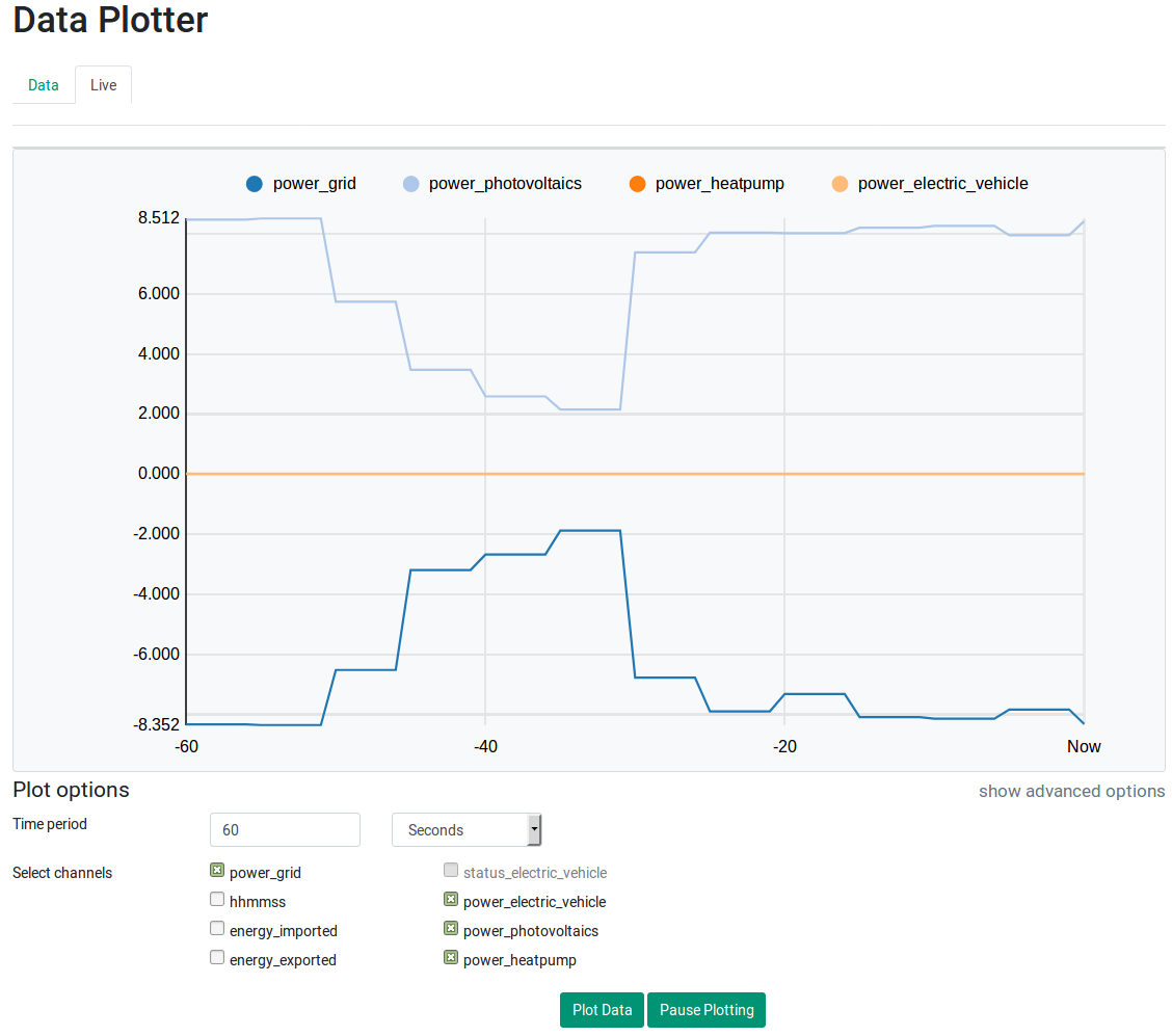
Let’s have look at the Data Plotter. To get to the Data Plotter click on Applications next to the OpenMUC logo and select Data Plotter.
Select the Live Data Plotter. To view the live data select the channels of your choice and click Plot Data.
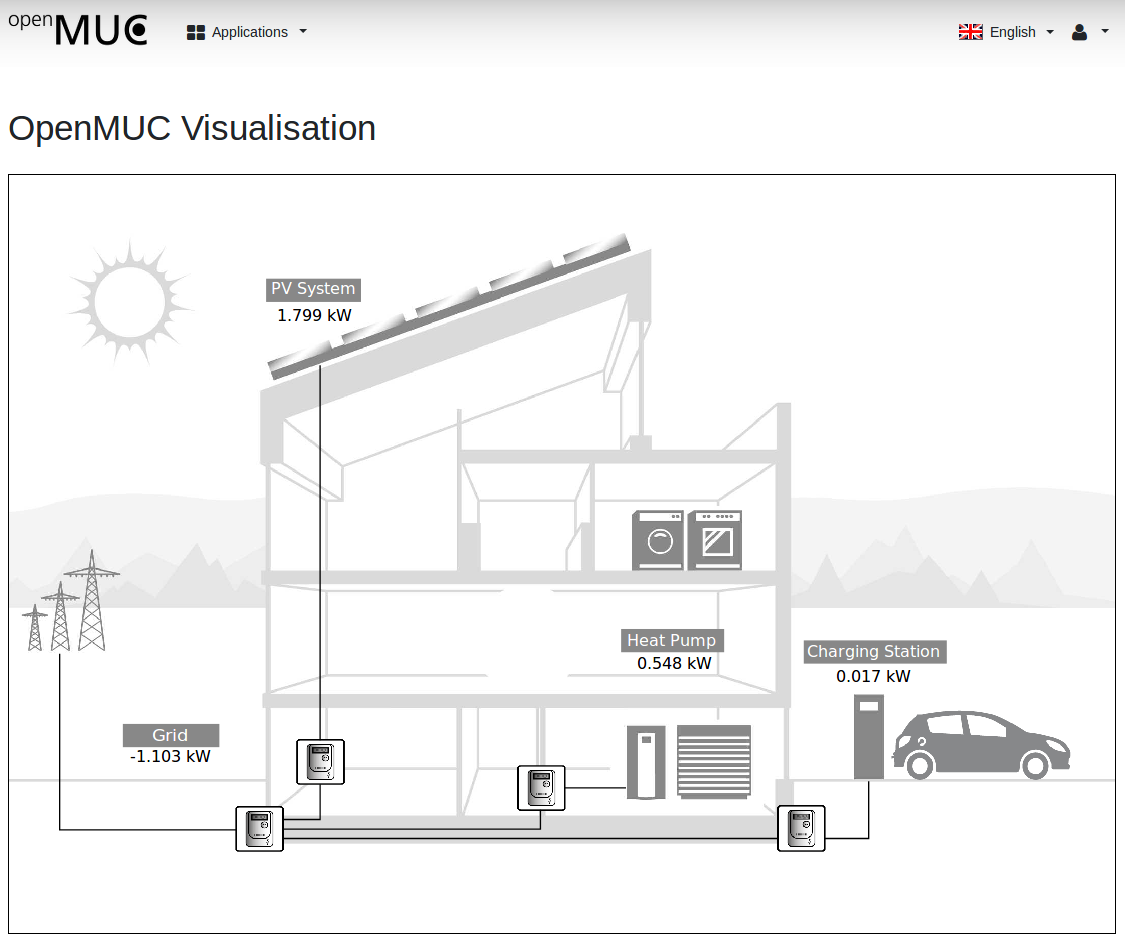
The last WebUI plugin we want to look at is a customised visualisation for our demo application. Click on Applications and select Simple Demo Visualisation. The purpose of this plugin is to show how OpenMUC channels can be accessed and used for individual visualisations. Detailed informations about the development of such a plugin can be found in the Tutorial Develop a Customised WebUI Plugin.
2.3.1. Add a New Channel
All channels currently defined get their data using the CSV driver from the file “csv-driver/home1.csv”. That file contains additional data. So let us now add a new channel to the OpenMUC configuration using the channel scan feature.
In the WebUI go to the Channel Configurator. Click the tab “Devices”. In the row of device “home1” click on the search/scan icon. It shows you all the channels available in that device. Once the scan has completed a list of available channels is shown. In this tutorial we select the channel with address “pv_energy_production”. Click “add channels”.
Now the channel overview opens where we can find our selected channel. In the last step of the configuration we click on the edit icon of the channel and set the parameters logging interval and sampling interval to 5000 ms and change the unit to kWh.
You can now check that the new channel was added to the “conf/channels.xml” file.
After submitting the channel configuration we go back to the dashboard and open the Channel Access Tool. Here we select our home1 device and continue with access selected. Now we able to see the current values of the pv_energy_production channel.
The logged data can be found in openmuc/framework/data/ascii/<currentdate>_5000.dat
3. Tutorials
3.1. Build a Simple M-Bus Data Logger
Objective: You will learn how to create a simple data logger which reads out a M-Bus meter via serial communication. It uses OpenMUC on-board tools so no programming is required.
Preparation: If not already done, your system needs to be prepared once for serial communication.
sudo apt-get install librxtx-java
sudo adduser $USER dialout
Now logout from your system and login again to apply system changes.
Step-by-step
-
Download OpenMUC and unpack it
-
Open openmuc/framework/conf/bundles.conf.gradle and comment the following lines by //
osgibundles group: "org.openmuc.framework", name: "openmuc-app-simpledemo", version: openmucVersion
osgibundles group: "org.openmuc.framework", name: "openmuc-driver-csv", version: openmucVersion
-
Add following lines to make the M-Bus driver and serial communication available
osgibundles group: "org.openmuc.framework", name: "openmuc-driver-mbus", version: openmucVersion
osgibundles group: "org.openmuc", name: "jrxtx", version: "1.0.1"
-
To apply changes navigate to openmuc/framework/bin and run
./openmuc update-bundles
-
Start OpenMUC
./openmuc start -fg
-
Open a browser and point it to localhost:8888 to view the WebUI of OpenMUC. Login with user admin and password admin.
-
Click on Channel Configurator > Tab Drivers > Add new driver to configuration
-
Enter mbus as ID and click Submit
-
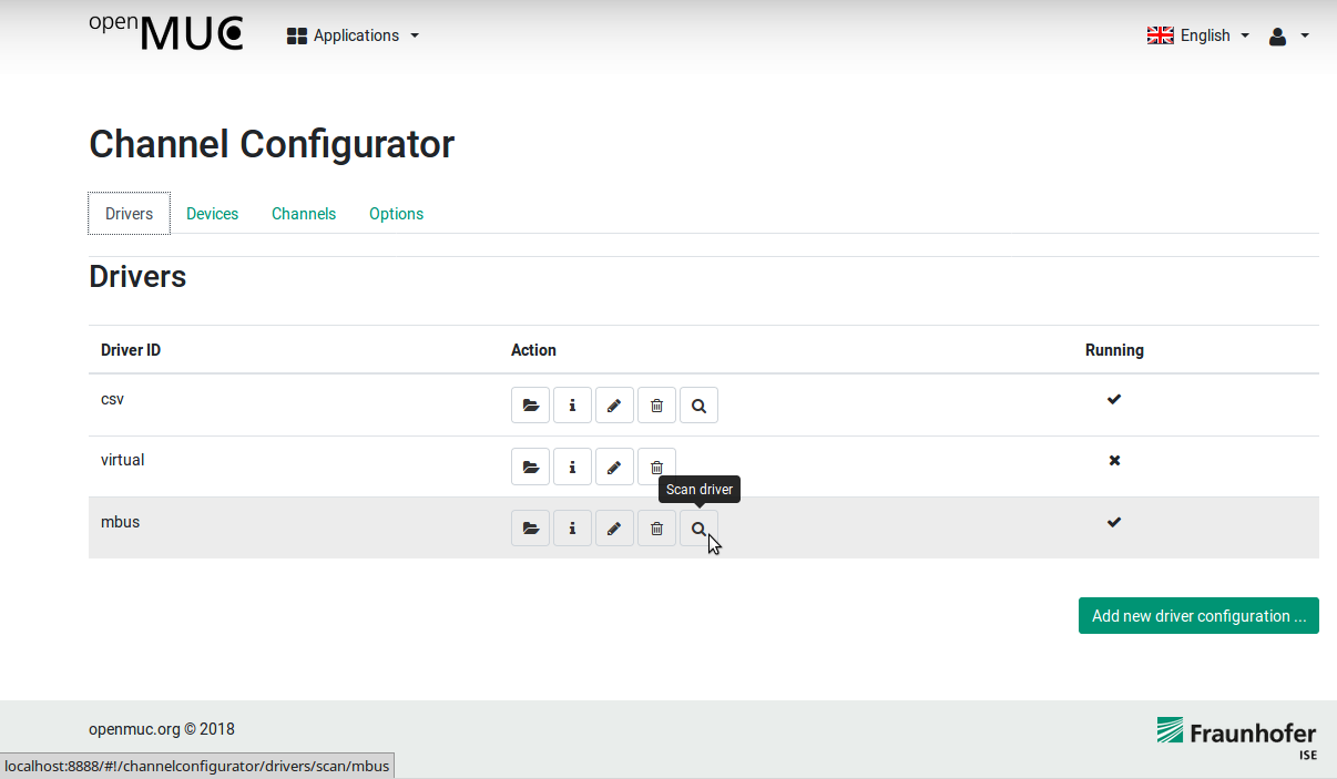
Now the M-Bus driver appears under Channel Configurator > Tab Drivers. Click on the search icon
-
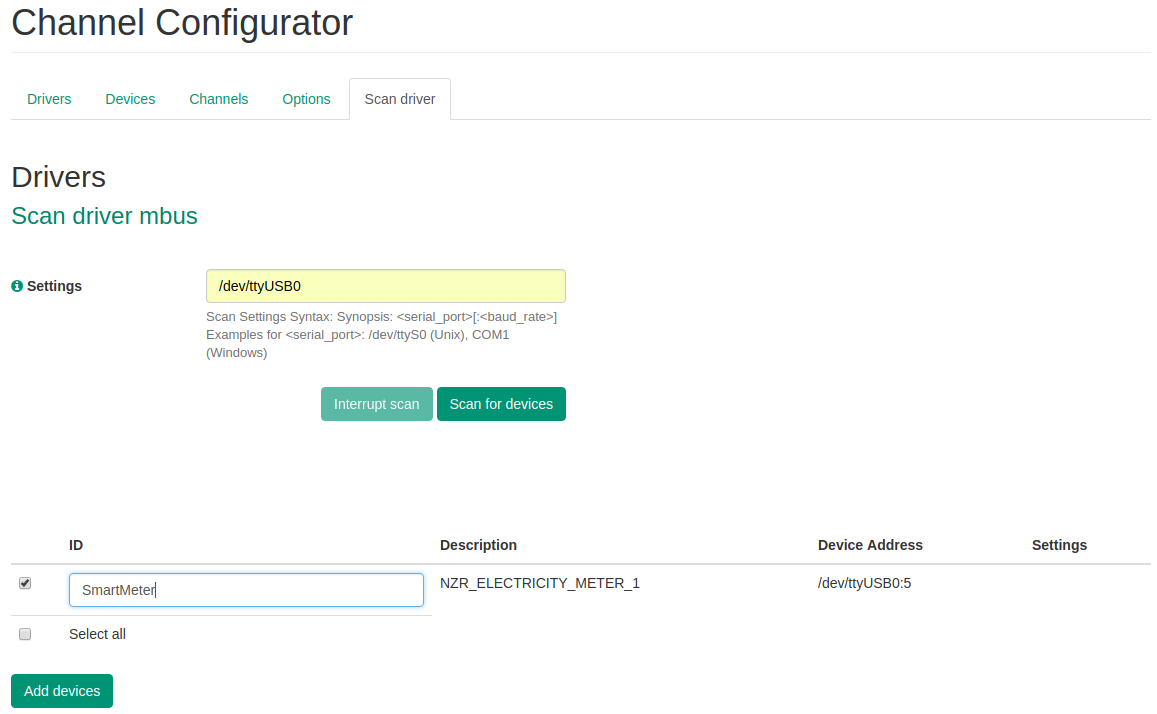
Enter the serial port the meter is connected to and provide the baud rate if needed (e.g. /dev/ttyS0 or /dev/ttyS0:2400). See M-Bus driver section for more information. If you are using an USB device you can use the dmesg tool on linux to figure out on what port it is connected (e.g. /dev/ttyUSB0).
-
Click on Scan for devices. Now OpenMUC scans all M-Bus addresses, which may take a while
-
Select the desired device from the list and click Add devices
-
Now the device is added. If you do not see the search icon next to the device, press F5 to reload the page and navigate to Channel Configurator > Tab Devices
-
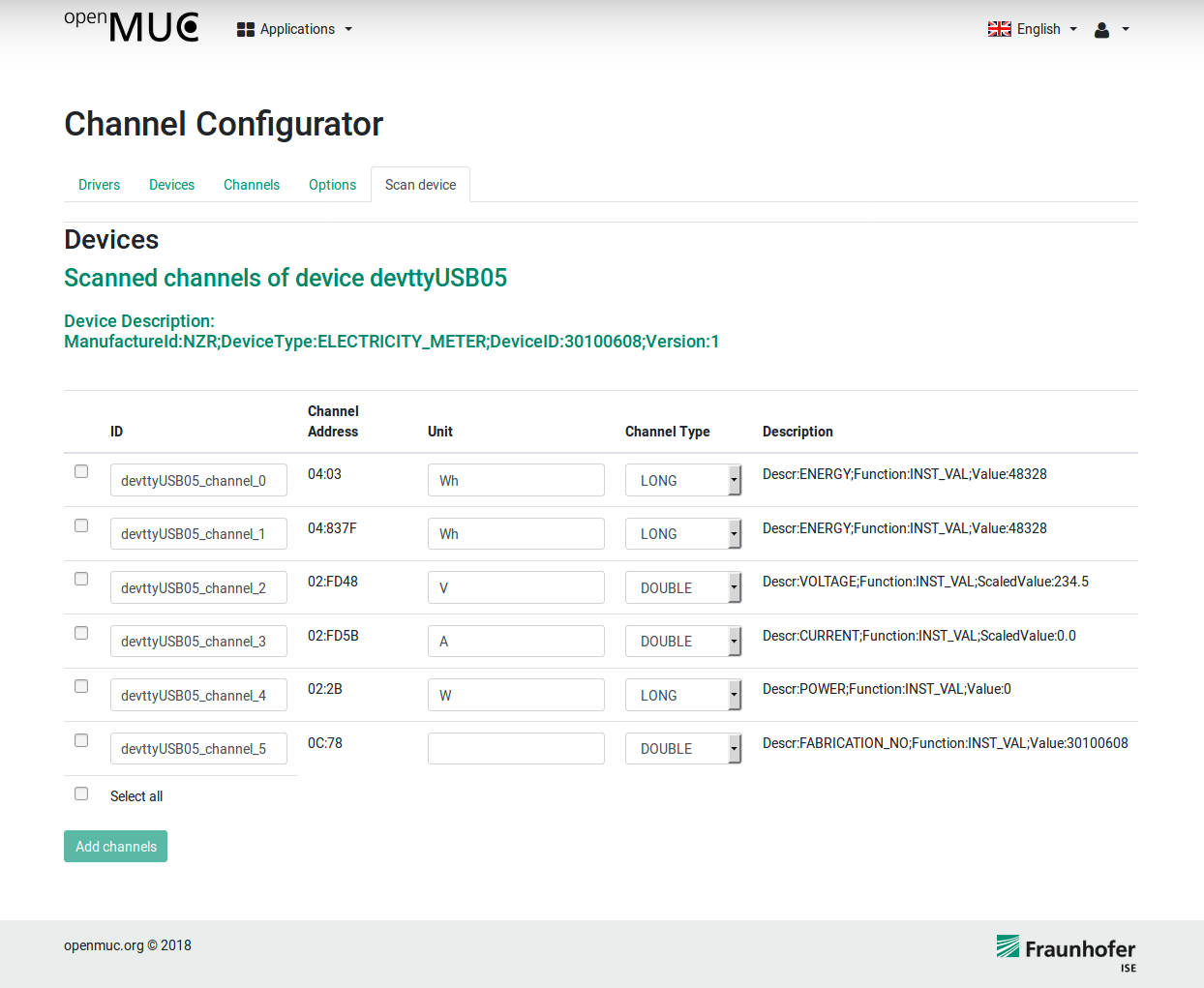
Click on the search icon and OpenMUC automatically scans all available channels. Select the desired channels and click Add channels
-
Now we need to define a sampling and logging interval for the channels. Click on Channel Configurator > Tab Channels and click on Edit Icon of the desired channel. Write 2000 in the Sampling Interval and Logging Interval field and click Submit
-
To show actual values of the channel, navigate to Applications > Channel Access Tool, select your device and click Access selected
Tips
-
All logged data are stored in /openmuc/framework/data/ascii/
-
You can also change the configuration by editing /openmuc/framework/conf/channels.xml
3.2. Develop a Customised Application
Objective: You will learn how to develop your own OpenMUC application. This tutorial focuses on the Eclipse integration, build process and how to start your application in the felix OSGi framework.
Preparation: This tutorial is based on Eclipse IDE and Gradle build tool, therefore you need Eclipse IDE and Gradle installed on your pc.
Step-by-step
-
Download and unpack the OpenMUC framework. Open a terminal and navigate to the openmuc folder
-
Create a new project based on the simple demo application. Navigate to openmuc/projects/app and copy the simpledemo folder and rename the copy to ems (Energy Management System).
-
Edit the build.gradle file inside your ems folder. Rename the project name and description and save the file.
def projectName = "EMS"
...
description "OpenMUC Energy Management System."
-
Navigate to app/ems/src/main/java/org/openmuc/framework/app/ and rename the folder simpledemo to ems
-
Replace the SimpleDemoApp.java inside this ems folder with EmsApp.java.
package org.openmuc.framework.app.ems;

import org.openmuc.framework.data.Record;
import org.openmuc.framework.dataaccess.Channel;
import org.openmuc.framework.dataaccess.DataAccessService;
import org.openmuc.framework.dataaccess.RecordListener;
import org.osgi.service.component.annotations.Activate;
import org.osgi.service.component.annotations.Component;
import org.osgi.service.component.annotations.Deactivate;
import org.osgi.service.component.annotations.Reference;
import org.slf4j.Logger;
import org.slf4j.LoggerFactory;

@Component(service = {})
public final class EmsApp{

	private static final Logger logger = LoggerFactory.getLogger(EmsApp.class);
	private static final String APP_NAME = "OpenMUC EMS App";

	private Channel chPowerGrid;
	private RecordListener powerListener;

	@Reference
	private DataAccessService dataAccessService;

	@Activate
	private void activate() {
		logger.info("Activating {}", APP_NAME);
		powerListener = new PowerListener();
		chPowerGrid = dataAccessService.getChannel("power_grid");
		chPowerGrid.addListener(powerListener);
	}

	@Deactivate
	private void deactivate() {
		logger.info("Deactivating {}", APP_NAME);
		chPowerGrid.removeListener(powerListener);
	}
}

class PowerListener implements RecordListener{

	private static final Logger logger = LoggerFactory.getLogger(PowerListener.class);

	@Override
	public void newRecord(Record record) {
		if (record.getValue() != null) {
			logger.info(">>> grid power: {}", record.getValue().asDouble());
		}
	}
}
This is a light version of the simple demo application and basically adds a listener to the power_grid channel and logs the current value. This class can be used for further development of your application.
-
Now we add our project to the gradle build process. For this purpose open the openmuc/settings.gradle in an editor and append following statement to the include statement
, "openmuc-app-ems"
-
Furthermore you need to add following line at the end of settings.gradle
project(":openmuc-app-ems").projectDir = file("projects/app/ems") -
Now we create the Eclipse project files by running the following command in the openmuc main directory
gradle eclipse
-
Start your Eclipse IDE and set the GRADLE_USER_HOME classpath variable: Go to Window>Preferences>Java>Build Path>Classpath Variable. Set the variable GRADLE_USER_HOME to the path of the ~/.gradle folder in your home directory (e.g. /home/<user_name>/.gradle/
-
Import the Openmuc projects into Eclipse: Go to File>Import>General>Existing Projects into Workspace, select your OpenMUC directory and click on Finish. All projects should be imported without any errors.
-
Now add the EMS application to the OpenMUC Framework. Navigate openmuc/framework/conf and and following line to bundles.conf.gradle below the openmuc-app-simpledemo entry:
osgibundles group: "org.openmuc.framework", name: "openmuc-app-ems", version: openmucVersion
-
Finally we build the framework and start our application. Navigate to openmuc/framework/bin and run:
./openmuc update-bundles -b
This will build all bundles and copies them to /openmuc/framework/bundles. Our EMS app should be now inside this folder e.g. openmuc-app-ems-<version>.jar
-
Start the framework with:
./openmuc start -fg
-
The log messages of our EMS application are now visible in the terminal e.g:
2018-12-17 19:10:20.015 [...] INFO  o.o.framework.app.simpledemo.EmsApp - >>> grid power: -1.779
2018-12-17 19:10:25.006 [...] INFO  o.o.framework.app.simpledemo.EmsApp - >>> grid power: -1.761
-
Now you know all the steps to build a new application and get it running in OpenMUC. For further development you should have a look at the source code of the SimpleDemoApp.java.
3.3. Develop a Customised WebUI Plugin
Objective: In this tutorial you will learn how to add a plugin to the WebUI as well as how to display data from your configured channels. Examples for such plugins are the simpledemovisualisation bundle or the HeiPhoss WebUI
| Note | This tutorial describes how we developed the simpledemovisualisation. When creating your own plugin you can just replace the name simpledemovisualisation whenever it comes up in the tutorial. |
Preparation: You should be familiar with OpenMUC’s architecture.
Step-by-step
-
First we have to create a new Project with the Structure
openmuc/projects/webui/simpledemovisualisation
-
Now copy the build.gradle file from one of the existing WebUI plugins, for example:
openmuc/projects/webui/channelaccesstool/build.gradle
into this project and change the projectName and projectDescription
def projectName = "OpenMUC WebUI - Simple Demo Visualisation"
def projectDescription = "Simple Demo Visualisation plug-in for the WebUI of the OpenMUC framework."
-
Open openmuc/configuration.gradle and add the following line under distributionProjects = javaProjects.findAll
it.getPath() == ":openmuc-webui-simpledemovisualisation" ||
-
Open openmuc/settings.gradle and add the following line under OpenMUC WebUI Bundles of the include section
'openmuc-webui-simpledemovisualisation',
-
Furthermore, add the following line to the projects section of the settings.gradle
project(":openmuc-webui-simpledemovisualisation").projectDir = file('projects/webui/simpledemovisualisation') -
Open openmuc/framework/conf/bundles.conf.gradle and add the following line under dependencies
osgibundles group: "org.openmuc.framework", name: "openmuc-webui-simpledemovisualisation", version: openmucVersion
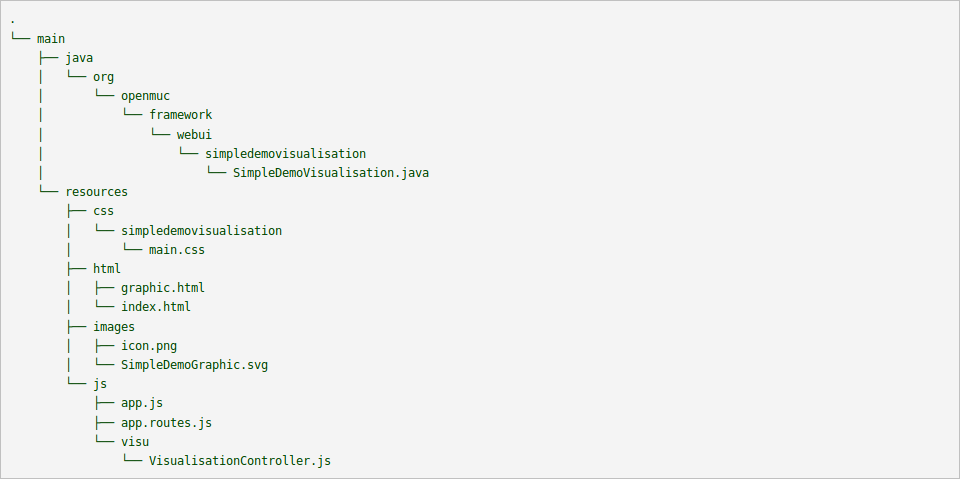
Next we will take a look at how our project should be structured once we are done
-
First we will take a look at the java file. Recreate the folder structure above and create the java file SimpleDemoVisualisation.java, and then copy this into it
import org.openmuc.framework.webui.spi.WebUiPluginService;
import org.osgi.service.component.annotations.Component;

@Component(service = WebUiPluginService.class)
public final class SimpleDemoVisualisation extends WebUiPluginService {

    @Override
    public String getAlias() {
        return "simpledemovisualisation";
    }

    @Override
    public String getName() {
        return "Simple Demo Visualisation";
    }

}
The two functions getAlias and getName have to be overridden. The alias is used to identify the plugin while the name will be displayed in the WebUI. In order to display an icon above the plugin’s name, the file needs to be called icon and put in the images folder.
-
Next we will take a look at app.js and app.routes.js. In app.js all we do is creating a module and naming it.
(function(){
        angular.module('openmuc.openmuc-visu', []);
})();
The more interesting one is app.routes.js because it is responsible for allowing us to get from the main page to the page of our plugin. It also allows us to specify which files have to be loaded.
(function(){

    var app = angular.module('openmuc');

    app.config(['$stateProvider', '$urlRouterProvider',
        function($stateProvider, $urlRouterProvider) {
            $stateProvider.
            state('simpledemovisualisation', {
                url: '/simpledemovisualisation',
                templateUrl: 'simpledemovisualisation/html/index.html',
                requireLogin: true
            }).
            state('simpledemovisualisation.index', {
                url: '/',
                templateUrl: 'simpledemovisualisation/html/graphic.html',
                controller: 'VisualisationController',
                requireLogin: true,
                resolve: {
                    openmuc: function ($ocLazyLoad) {
                        return $ocLazyLoad.load(
                            {
                                name: 'openmuc.simpledemovisualisation',
                                files: ['openmuc/js/channels/channelsService.js',
                                    'openmuc/js/channels/channelDataService.js',
                                    'simpledemovisualisation/css/simpledemovisualisation/main.css',
                                   'simpledemovisualisation/js/visu/VisualisationController.js']
                            }
                        )
                    }
                }
            })
        }]);

})();
All files you need have to be added to the list “files” in order for the plugin to work. The first two files we load are necessary to access the defined channels. Then we load in our css file and lastly the javascript file of this plugin.
-
For the Plugin created in this tutorial we will need an svg that is put into the image folder. The SimpleDemoGraphic.svg used in this tutorial is made up of multiple images, paths as well as text fields. In this case only the text fields are of interest.
-
The two html files used in this app are very simple, index.html sets the headline and then calls on graphic.html through ui-view. Ui-view calls upon the route defined in app.routes.js.
<div class="page-header">
    <h1>OpenMUC Visualisation</h1>
</div>
<div ui-view></div>
In graphic.html we create a div element and assign it the class svg-container. We then create an object HTML element inside the div and assign it the class svg-content.
<div class="svg-container">
  <object id="simpleDemoGraphic" type="image/svg+xml" data="simpledemovisualisation/images/SimpleDemoGraphic.svg"
  class="svg-content" onload="display_visualisation()"></object>
</div>
Further we also assign it an Id, in this case simpleDemoGraphic, specify that it is of the type svg and tell it where our svg is located. This way our svg is now displayed on the page, but in order to change elements of the svg we need a javascript function which is called through onload.
-
In order to specify how our page should be displayed we use a css file.
html, body {
    font-family: "Arial";
    margin: 0px;
    padding: 0px;
}

.svg-container {
    display: inline-block;
    position: relative;
    width: 1108px;
    height: 760px;
    border:1px solid black;
}

.svg-content {
    display: block;
    position: absolute;
    width: 1106px;
    height: 740px;
    top: 0;
    left: 0;
}
In this css file we tell the browser how the html elements should look and be positioned. If the declaration starts with a dot it signifies all elements with the specified class being targeted, a hash would signify an element with that Id being targeted and nothing signifies all html elements of that type should be targeted.
-
By default the svg will have an eight pixel margin on each side, meaning there will be white space between the border and svg. If you dont want that you need to open the svg in a text editor and add a style tag after the svg tag as shown below
<svg
   xmlns:osb="http://www.openswatchbook.org/uri/2009/osb"
   xmlns:dc="http://purl.org/dc/elements/1.1/"
   xmlns:cc="http://creativecommons.org/ns#"
   xmlns:rdf="http://www.w3.org/1999/02/22-rdf-syntax-ns#"
   xmlns:svg="http://www.w3.org/2000/svg"
   xmlns="http://www.w3.org/2000/svg"
   xmlns:xlink="http://www.w3.org/1999/xlink"
   xmlns:sodipodi="http://sodipodi.sourceforge.net/DTD/sodipodi-0.dtd"
   xmlns:inkscape="http://www.inkscape.org/namespaces/inkscape"
   width="100%"
   height="100%"
   viewBox="0 0 573.61664 357.1875"
   version="1.1"
   id="svg8"
   inkscape:version="0.92.3 (2405546, 2018-03-11)"
   sodipodi:docname="SimpleDemoGraphic.svg">
  <style
     type="text/css"
     media="screen"
     id="style5004"><![CDATA[
      body{
         margin: 0px;
      }
    ]]></style>
We cannot change the css of the svg from our css file so we have to do it inside the svg.
-
Finally we take a look at the javascript file that will allow us to display data in real time.
(function(){

    var injectParams = ['$scope', '$interval', 'ChannelsService'];

    var VisualisationController = function($scope, $interval, ChannelsService) {
        var svg_document;

        display_visualisation = function() {
Here we “import” the angular functions $scope and $interval as well as the class ChannelsService. Next we take a look at the function display_visualisation that is called when the html page loads.
svg_document = document.getElementById('simpleDemoGraphic').contentDocument;Through this line of code we now have access to the svg in javascript. We achieve this by calling document.getElementById with the id of our object element as a parameter. The contentDocument means that the return value is the document object, otherwise the return would have just been the content of the document, in which case we could not use it in the way we need to later.
    $scope.interval = "";
    $interval.cancel($scope.interval);
    $scope.interval = $interval(function(){
        ...
    }, 500);
};
What follows is defined inside this interval, meaning it will be repeated every 500 milliseconds.
ChannelsService.getAllChannels().then(async function(channels) {
                    $scope.channels = await channels.records;
});
Here we call the function getAllChannels of the class ChannelsService. It makes a get call to the REST server and returns all the channels defined in the channels.xml. The “then” means that whatever is in the round brackets will be executed after getAllChannels' return value arrives. Inside these round brackets we define an async function with getAllChannels' return value as a parameter. The list records of the return value contains the requested channels, so we save them in the list $scope.channels. Normally the rest of the code would be executed while getAllChannels waits for a reply, in which case our code would fail as $scope.channels would be undefined, but the await keyword in conjunction with marking the function as async makes it so the code only resumes executing once the await has been resolved.
if ($scope.channels != undefined){
    $scope.channels.forEach(function(channel){
        if (channel.id === "power_heatpump"){
            textHeatPump = svg_document.getElementById("textHeatPump");
            textHeatPump.textContent = channel.record.value + " kW";
        }
        if (channel.id === "power_electric_vehicle"){
            textChargingStation = svg_document.getElementById("textChargingStation");
            textChargingStation.textContent = channel.record.value + " kW";
        }
        if (channel.id === "power_photovoltaics"){
            textPv = svg_document.getElementById("textPv");
            textPv.textContent = channel.record.value + " kW";
        }
        if (channel.id === "power_grid"){
            textGrid = svg_document.getElementById("textGrid");
            textGrid.textContent = channel.record.value + " kW";
        }
    });
}
First we check if our list is not undefined as it is possible that during the first interval there wont be any data to work with. Now we iterate through our channels list to find the channels we need. Once we found the right channel, we search for the corresponding text field and save the reference to it in a variable. By setting the textContent of the text field we can change what is displayed, in this case the channel’s value is displayed in the text field. Now we set the interval and close the function definition as shown above.
        $scope.$on('$destroy', function () {
            $interval.cancel($scope.interval);
        });

        };

    VisualisationController.$inject = injectParams;

    angular.module('openmuc.openmuc-visu').controller('VisualisationController', VisualisationController);

})();
After that we tell the function to stop the interval if the scope’s destroy event is triggered and that the in app.js defined module should use this controller.
Tips
-
If you want to change the css of the svg at runtime you can do so through javascript similarly to the manipulation of the text field above.
textHeatPump.style.fill = "blue";This would set the text color of the text field to blue
4. Architecture
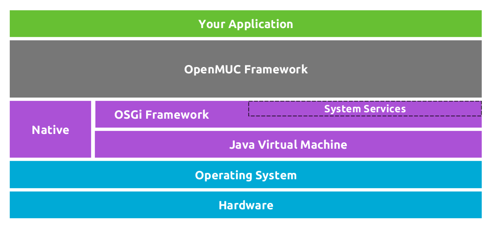
The following image depicts the software layers of an OpenMUC system.
The OpenMUC framework runs within an OSGi environment which in turn is being run by a Java Virtual Machine. The underlying operating system and hardware can be chosen freely as long as it can run a Java 8 VM.
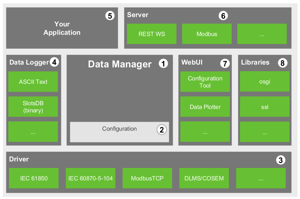
OpenMUC consists essentially of various software modules which are implemented as OSGi bundles that run in the OSGi environment and communicate over OSGi services. The following figure illustrates the main modules that make up OpenMUC.
All modules except for the data manager are optional. Thus by selecting the modules you need you can easily create your own customized and lightweight system.
The different modules in the picture are now further explained:
-
The data manager represents the core and center of OpenMUC. Virtually all other OpenMUC modules (e.g. drivers, data loggers, servers, applications and web interface plugins) communicate with it through OSGi services. The data manager gets automatically notified when new drivers or data loggers get installed. OpenMUC applications communicate with devices, access logged data or change the configuration by calling service functions provided by the data manager. It is therefore the data manager that shields the application programmer from the details of the communication and data logging technology. What the data manager does is mostly controlled through a central configuration.
-
The channel configuration holds the user defined data channels and its parameters. Data channels are the frameworks representation of data points in connected devices. Amongst others the channel configuration holds the following information:
-
communication parameters that the drivers require
-
when to sample new data from connected devices
-
when to send sampled data to existing data logger(s) for efficient persistent storage. The configuration is stored in the file conf/channels.xml. You may add or modify the configured channels by manually editing the channels.xml file or through the channel configurator web interface.
-
-
A driver is used by the data manager to send/get data to/from a connected device. Thus a driver usually implements a communication protocol. Several communication drivers have already been developed (e.g. IEC 61850, ModbusTCP, KNX, DLMS/COSEM). Many drivers use standalone communication libraries (e.g. OpenIEC 61850, jMBus) developed by the OpenMUC team. These libraries do not depend on the OpenMUC framework and can therefore be used by any Java application. New communication drivers for OpenMUC can be easily developed by third parties.
-
A data logger saves sampled data persistently. The data manager forwards sampled data to all available data loggers if configured to do so. Data loggers are specifically designed to store time series data for short storage and retrieval times. OpenMUC currently includes four data loggers. The ASCII data logger saves data in a human readable text format while SlotsDB saves data in a more efficient binary format. And two loggers for remote system logging with AMQP or MQTT.
-
If all you want is sample and log data then you can use the OpenMUC framework as it is and simply configure it to your needs. But if you want to process sampled data or control a device you will want to write your own application. Like all other modules your application will be an OSGi bundle. In your application you can use the DataAccessService and the ConfigService provided by the data manager to access sampled and logged data. You may also issue immediate read or write commands. These are forwarded by the data manager to the driver. The configuration (when to sample and to log) can also be changed during run-time by the application. At all times the application only communicates with the data manager and is therefore not confronted with the complicated details of the communication technology being used.
-
If your application is located on a remote system (e.g. a smart phone or an Internet server) then the data and configuration can be accessed through an OpenMUC server. At the moment OpenMUC provides a RESTful web service for this purpose.
-
The OpenMUC framework provides a web user interface (WebUI) for tasks such as configuration, visualization of sampled data or exporting logged data. The web interface is modular and provides a plug-in interface. This way developers may write a website that integrates into the main menu of the web interface. The WebUI is mostly for configuration and testing purposes. Most companies will want to create their own individual UI.
-
OpenMUC also contains a set of core libraries which provide helper classes that are used by multiple bundles of the framework.
4.1. File Structure of the Distribution
The distribution contains the following important files and folders:
- build/libs-all
-
All modules/bundles that make up the OpenMUC framework
- dependencies
-
Information on the external dependencies of the OpenMUC framework. Also contains the RXTX library (repacked as a bundle) which is needed by many OpenMUC drivers based on serial communication.
- projects
-
All sources of the OpenMUC framework. You can easily change and rebuild OpenMUC using Gradle.
- framework
-
A ready to use OpenMUC demo framework that is introduced next.
4.2. Folder framework/
The folder “framework” contains a configured OpenMUC framework that can be used as a basis to create your own customized OpenMUC framework for your task. The framework folder contains the following important files and folders:
- felix
-
The main Apache Felix OSGi jar which is run to start OpenMUC.
- bin
-
Run scripts for Linux/Unix and Windows.
- bundle
-
Contains all bundles that are started by the Felix OSGi framework. Note that this folder does not contain all available OpenMUC bundles but only a subset for demonstration purposes.
- log
-
Log files produced by the running framework.
- conf
-
Various configuration files of the framework.
4.2.1. Folder conf/
- bundles.conf.gradle
-
Contains a list of all bundles which should be used for the framework.
- channels.xml
-
Configuration file of OpenMUC to configure drivers, devices and channels.
- config.properties
-
Property file of the Felix OSGi framework.
- logback.xml
-
Configuration file to configure log levels for console and log file.
Currently, the logging is configured to create logfiles of at most 100MB, create a new log file every day and keep a maximum of 30 days or 3GB, which ever is reached first.
- system.properties
-
Contains general settings for the OpenMUC framework
4.3. Devices and Channels
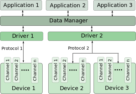
OpenMUC works on the basis of channels. A channel basically represents a single data point. Some examples for a channel are the metered active power of a smart meter, the temperature of a temperature sensor, any value of digital or analog I/O module or the some manufacture data of the device. Thus a channel can represent any kind of data point. The following picture illustrates the channel concept.
4.4. Configuration via channels.xml
The conf/channels.xml file is the main configuration file for OpenMUC. It tells the OpenMUC framework which channels it should log and sample. It contains a hierarchical structure of drivers, devices and channels. A driver can have one or more devices and devices can have one or more channels. Following listing shows a sample configuration to illustrate the hierarchical structure. The driver, device and channel options are explained afterwards.
<?xml version="1.0" encoding="UTF-8" standalone="no"?>
<configuration>
        <logger>loggerId</logger>

        <driver id="driver_x">
                <!-- driver options -->
                <device>
                        <!-- device options -->
                        <channel>
                                <!-- channel options -->
                        </channel>
                        <channel>
                                <!-- channel options -->
                        </channel>
                </device>
        </driver>
</configuration>| Options | Mandatory | Values | Default | Description |
|---|---|---|---|---|
id | yes | string | – | Id of the driver |
samplingTimeout | no | time* | 0 | Default time waited for a read operation to complete if the device doesn’t set a samplingTimeout on its own. |
connectRetryInterval | no | time* | 60s | Default time waited until a failed connection attempt is repeated. |
disabled | no | boolean | false | While disabled, no connections to devices on this driver are established at all and all channels of these devices stop being sampled and logged. |
| Options | Mandatory | Values | Default | Description |
|---|---|---|---|---|
id | no | string | – | ID of the device. |
deviceAddress | yes | string | – | Address for the driver to uniquely identify the device. Syntax of this address is up to the driver implementation. |
description | no | string | – | Description of the device. |
settings | no | string | – | Additional settings for the driver. Syntax is up to the driver implementation. |
samplingTimeout | no | time* | 0 | Time waited for a read operation to complete. Overwrites samplingTimeout of Driver. |
connectRetryInterval | no | time* | 60s | Time waited until a failed connection attempt is repeated. |
disabled | no | boolean | false | While disabled, no connection of this device is established and all channels of this device stop being sampled and logged. |
| Options | Mandatory | Values | Default | Description |
|---|---|---|---|---|
id | yes | string | – | Globally unique identifier. Used by data logger implementations. The OpenMUC framework automatically generates an id if none is provided. |
description | no | string | – | Description of the channel. |
channelAddress | yes | string | – | The channelAddress is driver specific and contains the necessary parameters for the driver to access. |
settings | no | string | – | Additional settings for the driver. Syntax is up to the driver implementation. |
valueType | no | DOUBLE | DOUBLE | Data type of the channel. Used on data logger. Driver implementation do NOT receive this settings! |
valueType Attribute: length | no | integer | 10 | The attribute length is only used if valueType is BYTE_ARRAY or STRING. Determines the maximum length of the byte array or string. |
scalingFactor | no | double | 1 | Is used to scale a value read by a driver or set by an application. The value read by an driver is multiplied with the scalingFactor and a value set by an application is divided by the scalingFactor. Possible values are e.g.: 1.0 4.94147E-9 -2.4 |
valueOffset | no | double | 0 | Is used to offset a value read by a driver or set by an application. The offset is added to a value read by a driver and subtracted from a value set by an application. |
unit | no | string | – | Physical unit of this channel. For information only (info can be accessed by an app or driver) |
loggingInterval | no | time* | – | Time difference until this channel is logged again. Omitting loggingInterval disables logging in intervals. Setting loggingInterval disables loggingEvent. |
loggingTimeOffset | no | time* | 0 | |
loggingEvent | no | boolean | false | If true, immediately logs latest record on value change. Only supported by some data loggers. Disabled if loggingInterval is set. See data logger description for more information. |
loggingSettings | no | string | – | Data logger specific log settings. Format: <loggerId_A>[:<param_A>=<value_A>][,…][;<loggerId_B>[:<param_B>=<value_B>]]. See data logger description for more information. |
loggingSettings Attribute: reader | no | string | – | In case multiple readers are registered in the framework you can use the attribute reader to specify a dedicated logger for reading values e.g. <loggingSettings reader=”asciilogger”>mqttlogger:topic=my/topic</loggingSettings |
listening | no | boolean | false | Determines if this channel shall passively listen for incoming value changes from the driver. |
samplingInterval | no | time* | – | Time interval between two attempts to read this channel. -1 or omitting samlingOffset disables sampling on this channel. |
samplingTimeOffset | no | time* | 0 | |
samplingGroup | no | string | – | For grouping channels. All channels with the same samplingGroup and same samplingInterval are in one group. The purpous of samplingGroups is to improve the drivers performance – if possible. |
disabled | no | boolean | false | If a channel is disabled, all sampling and logging actions of this channel are stopped. |
*time: integer with suffix (ms, s, m, h) like: 300ms, 2s.
| Note | if you don’t use a suffix, then ms is automatically used |
The available driver settings, device settings and channel settings can also be found in the Javadoc of DriverConfig.java, DeviceConfig.java and ChannelConfig.java respectively.
Default Data Logger
You can define a default data logger by adding a logger element with the id of a data logger to the configuration. If available, that data logger is used to read logged values. The ids of data loggers shipped with the OpenMUC Framework are defined in the “Data Loggers” chapter. If no logger with the defined id is available, or the logger element is missing from the configuration, an arbitrary available logger is used to read logged values. Only one default logger may be defined. If multiple logger elements exists, only the first one is evaluated.
This configuration only affects reading of already logged values. Channels are still logged by all available loggers.
4.5. Sampling, Listening and Logging
-
sampling is when the data manager frequently asks a driver to retrieve a channel value.
-
listening is when the driver listens on a channel and forwards new values to the data manager.
-
logging is when the data manager forwards the current sampled value to the data loggers that are installed. The data loggers then store the data persistently
The following examples will give you a better understanding of these three settings.
<channel>
    <id>channel1</id>
    <channelAddress>dummy/channel/address/1</channelAddress>
    <samplingInterval>4s</samplingInterval>
</channel>
In example 1 the channel is sampled every 4 seconds which means the data manager requests every 4 seconds the current value from the driver.
<channel>
    <id>channel2</id>
    <channelAddress>dummy/channel/address/2</channelAddress>
    <samplingInterval>4s</samplingInterval>
    <loggingInterval>8s</loggingInterval>
</channel>
Example 2 extends example 1 by an additional logging. The logging interval is set to 8 seconds which means that every 8 seconds the last sampled value is stored in the database. In this case every second sampled value is stored because the sampling interval is 4 seconds. To log every sampled value the sampling interval and logging interval need to be the same.
<channel>
    <id>channel3</id>
    <channelAddress>dummy/channel/address/3</channelAddress>
    <listening>true</listening>
</channel>
In example 3 listening instead of sampling is used. This means that the driver reports a new channel value to the data manager when the value has changed for example.
 <channel>
    <id>channel4</id>
    <channelAddress>dummy/channel/address/4</channelAddress>
    <listening>true</listening>
    <loggingInterval>8s</loggingInterval>
</channel>
Example 4 extends example 3 by an additional logging.
| Important | When listening is true and additional a sampling interval is defined then the sampling is ignored. |
 <channel>
    <id>channel4</id>
    <channelAddress>dummy/channel/address/5</channelAddress>
    <listening>true</listening>
    <loggingEvent>true</loggingEvent>
</channel>
Example 5 extends example 3 by an additional event logging. It loggs only if only a new value was received. (the logger needs to support event logging)
5. OpenMUC Start Script
The script to start OpenMUC is located in /framework/bin/.
5.1. Start OpenMUC
To start OpenMUC on Linux run:
./bin/openmuc start -fg
This runs OpenMUC in the foreground on your console. If you like to start OpenMUC as background process then skip the parameter -fgbin\openmuc.batjava -jar felix/felix.jar
5.2. Stop OpenMUC
To stop OpenMUC run:
./bin/openmuc stop
If you started OpenMUC in the foreground you can press ctrl+d or enter “stop 0” to stop OpenMUC.
5.3. Restart OpenMUC
With the restart command OpenMUC stops and starts again.
./bin/openmuc restart
5.4. Reload OpenMUC Configuration
To reload the configuration without restarting OpenMUC use:
./bin/openmuc reload
5.5. Update Bundles
If you have modified the bundles.conf.gradle file then run the following command to update the /framework/bundle folder.
./bin/openmuc update-bundles
If you have changed the source code and want to rebuild the bundles and apply them to the /framework/bundle folder use:
./bin/openmuc update-bundles -b
If you are using a local maven repository you can use the -i option to update the repository with the latest changes.
./bin/openmuc update-bundles -i
Tip: development the following command is quite handy to start OpenMUC with your latest code changes:
./bin/openmuc update-bundles -b && ./bin/openmuc start -fg
5.6. Remote Shell
The remote shell allows you to connect via telnet to a running OpenMUC which was started as background process.
OpenMUC uses the Apache Felix Gogo JLine Shell by default, since JLine provides more advanced features than the standard GoGo Shell. Unfortunately, JLine does not work in combination with the remote shell. Therefore, we must switch back to the standard GoGo Shell to use remote access. This can be achieved by modifying the bundles.conf.gradle. Add the following bundles org.apache.felix.shell.remote and org.apache.felix.gogo.shell and comment or remove the bundles org.apache.felix.gogo.jline and jline
osgibundles group: "org.apache.felix",   name: "org.apache.felix.shell.remote",  version: "<version>"
osgibundles group: "org.apache.felix",   name: "org.apache.felix.gogo.shell",    version: "<version>"

//osgibundles group: "org.apache.felix", name: "org.apache.felix.gogo.jline",    version: "<version>"
//osgibundles group: "org.jline",        name: "jline",                          version: "<version>"
To access OpenMUC you can either use
./bin/openmuc remote-shell
or
telnet 127.0.0.1 6666
To exit the remote shell without stopping OpenMUC press ctrl+d.
5.7. Auto Start at Boot Time
On Debian based Linux distributions it is easy to configure automatic start of OpenMUC at boot time. As root execute the following commands:
ln -s /path/to/openmuc/bin/openmuc /etc/init.d/openmuc
update-rc.d openmuc defaults
The above solution will not work if the openmuc start script is located on a partion that is not yet mounted at the time the boot process attempts to open it. In this case you need copy the start script to /etc/init.d/ and edit it to set the OPENMUC_HOME variable.
6. Drivers
6.1. Install a Driver
For installing a new driver you have two possible ways.
6.1.1. Copy driver
Copy the corresponding driver jar file from the folder “build/libs-all/” to the “bundle” folder of the framework. Many drivers are “fat jars” which include their dependencies. An exception is the RXTX library which cannot be packed with the jars.
6.1.2. Editing bundles configuration
In /openmuc/framework/conf/bundles.conf.gradle you can find the list of all used bundles e.g.:
osgibundles group: "org.openmuc.framework", name: "openmuc-driver-csv", version: openmucVersion

osgibundles group: "org.openmuc.framework", name: "openmuc-webui-spi",  version: openmucVersion
osgibundles group: "org.openmuc.framework", name: "openmuc-webui-base", version: openmucVersion
If you want to add a new driver to the list, e.g. M-Bus, you can do this:
osgibundles group: "org.openmuc.framework", name: "openmuc-driver-csv",  version: openmucVersion
osgibundles group: "org.openmuc.framework", name: "openmuc-driver-mbus", version: openmucVersion
osgibundles group: "org.openmuc",           name: "jrxtx",               version: "1.0.1"

osgibundles group: "org.openmuc.framework", name: "openmuc-webui-spi",   version: openmucVersion
osgibundles group: "org.openmuc.framework", name: "openmuc-webui-base",  version: openmucVersion
Afterwards you have to execute in /openmuc/framework/bin/
./openmuc update-bundles
If this is the first time using ./openmuc update-bundles you have to add the parameter -i
./openmuc update-bundles -i
6.1.3. Use a Driver with Serial Communication
When you need to use a driver that uses serial communication you have to copy the RXTX bundle to the frameworks “bundle” folder.
cp ../dependencies/rxtx/jrxtx-1.0.1.jar ./bundle/
Additionally you need to install librxtx-java:
sudo apt-get install librxtx-java
The serial ports /dev/tty* are only accessible to members belonging to the group dialout. We therefore have to add our user to that group. E.g. using:
sudo adduser <yourUserName> dialout
6.2. Modbus
Modbus Homepage: http://www.modbus.org
Modbus Protocol Specifications: http://www.modbus.org/specs.php
Modbus Master Simulator modpoll: http://www.modbusdriver.com/modpoll.html
The Modbus driver supports RTU, TCP, UDP and RTU over TCP.
| TCP (ethernet) | UDP (ethernet) | RTU (serial) | RTUTCP (serial over ethernet) | |
|---|---|---|---|---|
Device Address | <ip>[:<port>] | <ip>[:<port>] | <serial port> | <ip>[:<port>] |
Settings | <type> | <type> | <type>:<encoding>:<baudrate>:<databits>:<parity>:<stopbits>:<echo>:<flowControlIn>:<flowControlOut> | <type> |
Channel Address | <UnitId>:<PrimaryTable>:<Address>:<Datatyp> | |||
DeviceAddress
For TCP, RTUTCP and UDP
The DeviceAddress is specified by an IP address and an optional port. If no port is specified, the driver uses the modbus default port 502.
For RTU:
The DeviceAddress is specified by a serial port like /dev/ttyS0.
| Note | The driver uses the j2mod library which itself uses the jSerialComm library for serial communication. |
Settings
| Config | Description/ Values |
|---|---|
<type> | RTU|TCP|RTUTCP|UDP |
<encoding> | SERIAL_ENCODING_RTU |
<baudrate> | Integer value: e.g.: 2400, 9600, 115200 |
<databits> | DATABITS_5, DATABITS_6, DATABITS_7, DATABITS_8 |
<parity> | PARITY_EVEN, PARITY_MARK, PARITY_NONE, PARITY_ODD, PARITY_SPACE |
<stopbits> | STOPBITS_1, STOPBITS_1_5, STOPBITS_2 |
<echo> | ECHO_TRUE, ECHO_FALSE |
<flowControlIn> | FLOWCONTROL_NONE, FLOWCONTROL_RTSCTS_IN, FLOWCONTROL_XONXOFF_IN |
<flowControlOut> | FLOWCONTROL_NONE, FLOWCONTROL_RTSCTS_OUT, FLOWCONTROL_XONXOFF_OUT |
<settings>
RTU:SERIAL_ENCODING_RTU:38400:DATABITS_8:PARITY_NONE:STOPBITS_1 :ECHO_FALSE:FLOWCONTROL_NONE:FLOWCONTROL_NONE
</settings>
ChannelAddress
The ChannelAddress consists of four parts: UnitId, PrimaryTable, Address and Datatyp which are explained in detail in the following table.
| Parameter | Description |
|---|---|
UnitId | In homogenious architecture (when just MODBUS TCP/IP is used) In heterogeneous architecture (when using MODBUS TCP/IP and MODBUS serial or MODBUS+) Note: Some MODBUS devices act like a bridge or a gateway and require the UnitId even if they are accessed through TCP/IP. One of those devices is the Janitza UMG. To access data from the Janitza the UnitId has to be 1. |
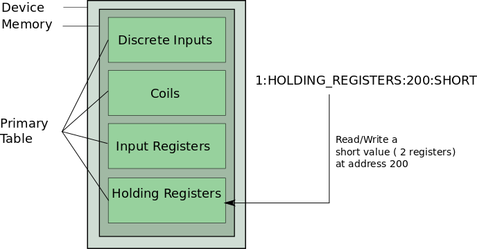
PrimaryTable | PrimaryTable defines the which part of the device memory should be accessed. Valid values: COILS, DISCRETE_INPUTS, INPUT_REGISTERS, HOLDING_REGISTERS |
Address | Address of the channel/register. Decimal integer value – not hex! |
Datatyp | Valid values: |
| Note | To store a UINT32 value it requires <valueType>LONG</valueType> for the channel. |
Valid Address Parameter Combinations
Since COILS and DISCRETE_INPUTS are used for bit access, only the data type BOOLEAN makes sense in combinations with of one of these. INPUT_REGISTERS and HOLDING_REGISTERS are used for register access. There is also a difference between reading and writing. Only COILS and HOLDING_REGISTERS are readable and writable. DISCRETE_INPUTS and INPUT_REGISTERS are read only. The following table gives an overview of valid parameter combinations of PrimaryTable and Datatyp.
| Primary Table | BOOLEAN | SHORT | INT | FLOAT | DOUBLE | LONG | BYTEARRAY[n] |
|---|---|---|---|---|---|---|---|
COILS | x | – | – | – | – | – | – |
DISCRETE_INPUTS | x | – | – | – | – | – | – |
INPUT_REGISTERS | – | x | x | x | x | x | x |
HOLDING_REGISTERS | – | x | x | x | x | x | x |
| Primary Table | BOOLEAN | SHORT | INT | FLOAT | DOUBLE | LONG | BYTEARRAY[n] |
|---|---|---|---|---|---|---|---|
COILS | x | – | – | – | – | – | – |
DISCRETE_INPUTS | – | – | – | – | – | – | – |
INPUT_REGISTERS | – | – | – | – | – | – | – |
HOLDING_REGISTERS | – | x | x | x | x | x | x |
<channelAddress>255:INPUT_REGISTERS:100:SHORT</channelAddress>
<channelAddress>255:COILS:412:BOOLEAN</channelAddress><channelAddress>255:INPUT_REGISTERS:100:BOOLEAN</channelAddress> (BOOLEAN doesn't
go with INPUT_REGISTERS)
<channelAddress>255:COILS:412:LONG</channelAddress> (LONG does not go with COILS)Function Codes (more detailed information about how the driver works)
The driver is based on the Java Modbus Library (j2mod) which provides read and write access via modbus. Following table shows which modbus function code is used to access the data of the channel.
| j2mod Method | Modbus Function Code | Primary Table | Access | Java Data Type |
|---|---|---|---|---|
ReadCoilsRequest | FC 1 Read Coils | Coils | RW | boolean |
ReadInputDiscretesRequest | FC 2 Read Discrete Inputs | Discrete Inputs | R | boolean |
ReadMultipleRegistersRequest | FC 3 Read Holding Registers | Holding Registers | RW | short, int, double, long, float, bytearray[] |
ReadInputRegistersRequest | FC 4 Read Input Registers | Input Registers | R | short, int, double, long, float, bytearray[] |
WriteCoilRequest | FC 5 Write Single Coil | Coils | RW | boolean |
WriteMultipleCoilsRequest | FC 15 Write Multiple Coils | Coils | RW | boolean |
WriteSingleRegisterRequest | FC 6 Write Single Register | Holding Registers | RW | short, int, double, long, float, bytearray[] |
WriteMultipleRegistersRequest | FC 16 Write Multiple Registers | Holding Registers | RW | short, int, double, long, float, bytearray[] |
Example
<channelAddress>255:INPUT_REGISTERS:100:SHORT</channelAddress> will be accessed
via function code 4.
6.2.1. Modbus TCP and Wago
| Note | Till now the driver has been tested with some modules of the Wago 750 Series with the Fieldbus-Coupler 750-342 |
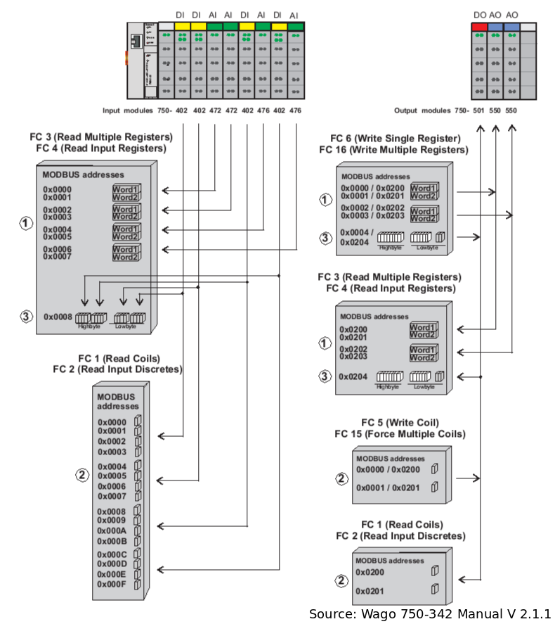
If you want to use the Modbus TCP driver for accessing a Wago device you first need to know how the process image is build. From the process image you can derive the register addresses of your Wago modules (AO, AI, DO, DI). You find detailed information about the process image in WAGO 750-342 Manual on page 46 and 47.
The following Examples are based on figure Wago 750-342 Process Image
*Example 1: Read AI 2 from first (left) 472-module (Register Address 0x0001)
<channelAddress>255:INPUT_REGISTERS:1:SHORT</channelAddress>Example 2: Read DI 3 from first (left) 472-module (Register Address 0x0003)
<channelAddress>255:DISCRETE_INPUTS:3:BOOLEAN</channelAddress>Example 3: Write AO 1 from first (left) 550-module (Register Address 0x0000/0x0200)
For writing only the +0x0200 addresses should be used! Since the driver accepts only a decimal channelAddress 0x0200 must be converted to decimal. The resulting address would be:
<channelAddress>255:HOLDING_REGISTERS:512:SHORT</channelAddress>Example 4: Write DO 2 from 501-module (Register Address 0x0000/0x0201)
For writing only the +0x0200 addresses should be used! Since the driver accepts only a decimal channelAddress 0x0201 must be converted to decimal. The resulting address would be:
<channelAddress>255:COILS:513:BOOLEAN</channelAddress>Example 5: Read back DO 2 from 501-module (Register Address 0x0201)
<channelAddress>255:COILS:513:BOOLEAN</channelAddress> or
<channelAddress>255:DISCRETE_INPUTS:513:BOOLEAN</channelAddress>6.3. M-Bus (wired)
M-Bus is communication protocol to read out meters.
| ID | mbus |
|---|---|
Device Address | <serial_port>:<mbus_address> or tcp:<host_address>:<port> |
Settings | [<baudrate>][:timeout][:lr][:ar][:d<delay>] [:tc<tcp_connection_timeout>] |
Channel Address | [X]<dib>:<vib> |
Device Address
<serial_port> – The serial port should be given that connects to the M-Bus converter. (e.g. /dev/ttyS0, /dev/ttyUSB0 on Linux).
<mbus_address> – The mbus adrdess can either be the the primary address or secondary address of the meter. The primary address is specified as integer (e.g. 1 for primary address 1) whereas the secondary address consits of 8 bytes that should be specified in hexadecimal form. (e.g. e30456a6b72e3e4e)
tcp – with this option M-Bus over TCP is used.
<host_address> – The host address for M-Bus over TCP e.g. 192.168.8.89.
<port> – The TCP port for M-Bus over TCP e.g. 5369
Settings
<baudrate> – If left empty the default is used: “2400”
<timeout> – Defines the read timeout in ms. Default is 2500 ms. Example: t5000 for timeout of 5 seconds
<lr> – Link reset before readout.
<ar> – Application reset before readout.
d<delay> – Inserts a delay between every message, including link reset and application reset. Delay in ms. A delay with 100 ms and activated link reset and application reset results in a total delay of 300 ms.
tc<tcp_connection_timeout> – The TCP connection timeout is need for a defined timeout when no TCP connection could established.
Channel Address
Shall be of the format <dib>:<vib> in a hexadecimal string format (e.g. 04:03 or 02:fd48) The X option is used for selecting a specific data record.
6.4. M-Bus (wireless)
Wireless M-Bus is communication protocol to read out meters and sensors.
| ID | wmbus |
|---|---|
Device Address | <serial_port>:<secondary_address> |
Settings | <transceiver> <mode> [<key>] |
Channel Address | <dib>:<vib> |
Device Address
<serial_port> – The serial port used for communication. Examples are /dev/ttyS0 (Linux) or COM1 (Windows)
<secondary_address> – The secondary address consists of 8 bytes that should be specified in hexadecimal form. (e.g. e30456a6b72e3e4e)
Settings
<transceiver> – The transceiver being used. It can be 'amber' or 'rc' for modules from RadioCrafts.
<mode> – The wM-Bus mode can be S or T.
<key> – The key in hexadecimal form.
Channel Address
Shall be of the format <dib>:<vib> in a hexadecimal string format (e.g. 04:03 or 02:fd48)
6.5. IEC 60870-5-104
IEC 60870-5-104 is an international communication standard for telecontrol. The IEC 60870-5-104 driver uses the library from the j60870 project.
The driver is able to send general interrogation commands for sampling. For writing almost all commands are possible.
| ID | iec60870 |
|---|---|
Device Address | [ca=<common_address>] [;p=<port>] [;h=<host_address>] |
Settings | [mft=<message_fragment_timeout>] [;cfl=<cot_field_length>] [;cafl=<common_address_field_length>] [;ifl=<ioa_field_length>] [;mtnar=<max_time_no_ack_received>] [;mtnas=<max_time_no_ack_sent>] [;mit=<max_idle_time>] [;mupr=<max_unconfirmed_ipdus_received>] [;sct=<stardt_con_timeout>] |
Channel Address | ca=<common_address>; t=<type_id>; ioa=<ioa> [;dt=<data_type>] [;i=<index>] [;m=<multiple>] |
All options are separated by a semicolon.
Channel Address
Mandatory options are Common Address, Type ID and Information Object Address.
It is possible to get a single value of a Sequence Information Element, for this you can define Index of the needed element. The first element is 0, the second 1, …
For reading values which are divided in multiple elements it can be defined how many elements should be read as one. e.g. i=0;m=4 says it reads from the first element up to the fourth element, of a sequence. This is only allowed for Binary State Information.
With the option Data Type it is possible to get a single quality flag.
| Data Type | Description |
|---|---|
v | value (default) |
ts | timestamp |
iv | in/valid |
nt | not topical |
sb | substituted |
bl | blocked |
ov | overflow |
ei | elapsed time invalid |
ca | counter was adjusted since last reading |
cy | counter overflow occurred in the |
6.6. IEC 61850
IEC 61850 is an international communication standard used mostly for substation automation and controlling distributed energy resources (DER). The IEC 61850 driver uses the client library from the OpenIEC61850 project.
| ID | iec61850 |
|---|---|
Device Address | <host>[:<port>] |
Settings | [-a <authentication parameter>] [-lt <local t-selector>] [-rt <remote t-selector>] |
Channel Address | <bda reference>:<fc> |
Channel Address
The channel address should be the IEC 61850 Object Reference and the Functional Constraint of the Basic Data Attribute that is to be addressed separated by a colon. Note that an IEC 61850 timestamp received will be converted to a LongValue that represents the milliseconds since 1970. Some information is lost during this conversion because the IEC 61850 timestamp is more exact.
Settings
The defaults for TSelLocal and TSelRemote are “00” and “01” respectively. You can also set either TSelector to the empty string (e.g. “-lt -rt”). This way they will be omitted in the connection request.
6.7. IEC 62056 part 21
The IEC 62056 part 21 driver can be used to read out meter via optical interface
| ID | iec62056p21 |
|---|---|
Device Address | <serial_port> |
Settings | [-d <baud_rate_change_delay>] [-t <timeout>] [-r <number_of_read_retries>] [-bd <initial_baud_rate>] [-a <device_address>] [-fbd] [-rsc <request_message_start_character>] |
Channel Address | <data_set_id> |
Device Address
<serial_port> – The serial port should be given that connects to the M-Bus converter. (e.g. /dev/ttyS0, /dev/ttyUSB0 on Linux).
Settings
Baud rate change delay -d sets the waiting time in milliseconds between a baud rate change default is 0.
Timeout -t sets the response timeout in milliseconds, default is 2000.
Number of read retries -r defines the maximum of read retries, default is 0.
Baud rate -bd sets a initial baud rate e.g. for devices with modem configuration, default is 300.
Device address -a is mostly needed for devices with RS485, default is no device address.
Fixed baud rate -fbd activates fixed baud rate, default is deactivated.
Request message start character -rsc is used for manufacture specific request messages. With this option you can change the default start character.
Read standard -rs reads the standard message and the manufacture specific message. This options has only an affect if the Request message start character is changed.
Channel Address
<data_set_id> – Id of the data set. It is usually an OBIS code of the format A-B:C.D.E*F or on older EDIS code of the format C.D.E.that specifies exactly what the value of this data set represents.
6.8. DLMS/COSEM
DLMS/COSEM is a international standardized protocol used mostly to communicate with smart meter devices. The DLMS/COSEM driver uses the client library developed by the jDLMS project. Currently, the DLMS/COSEM driver supports communication via HDLC and TCP/IP using Logical Name Referencing to retrieve values from the device.
Dependencies: rxtxcomm_api-2.1.7.jar (optional)
| ID | dlms |
|---|---|
Device Address | t=<serial/tcp> [;h=<inet_address>] [;p=<int>] [;hdlc=<boolean>] |
Settings | [SendDisconnect=<disconnect>];[UseHandshake=<handshake>];[..] [ld=<int>] [;cid=<cid>] [;sn=<sn>] [;emech=<emech>] [;amech=<amech>] |
Channel Address | <class-id>/<reference-id>/<attribute-id>[;t=<data_object_type>] |
Device Address
The interface address consists of all elements the driver needs to uniquely identify and address a physical smart meter and format depends on the used protocol. Refer to the following table for the format of the interface address.
| Option | Value | Mandatory | serial/tcp | default | Description |
|---|---|---|---|---|---|
t | serial/tcp | true | – | – | Connection type |
sp | string | false | serial | – | serial port e.g. sp=/dev/ttyS0 or sp=COM1 |
bd | integer | false | serial | 9600 | Baud rate |
h | integer | false | tcp | – | Host name e.g. h=127.0.0.1 |
p | integer | false | tcp | 4059 | Port |
hdlc | boolean | false | both | false | Uses HDLC if true |
d | integer | false | both | 0 | Baud rate change delay in milliseconds |
eh | flag | false | both | false | Use initial handshake to negotiate baud rate |
iec | string | false | both | – | IEC 21 address |
pd | integer | false | both | 0 | Physical Device Address |
Serial with HDLC on serial port ttyUSB0 an 9600 baud:
t=serial;sp=/dev/ttyUSB0;bd=9600;hdlc=true
TCP with HDLC to host 192.168.85.99 on port 5081:
t=tcp;h=192.168.85.99;p=5081;hdlc=true
Settings
Settings are separated by a semi-colon. The available settings are determined by the used protocol, defined as first parameter of the device address. All possible settings with a short description and default values are listed in the following table.
| Option | Value | Mandatory | Default | Description |
|---|---|---|---|---|
ld | integer | false | 1 | Logical Device Address |
cid | integer | false | 16 | Client ID |
sn | boolean | false | false | use SN referencing |
emech | integer | false | -1 | Encryption Mechanism |
amech | integer | false | 0 | Authentication Mechanism |
ekey | hex_value | false | – | Encryption Key |
akey | hex_value | false | – | Authentication Key |
pass | string | false | – | Authorisation password to access the smart meter device |
cl | integer | false | 16 | Challenge Length |
rt | integer | false | 20000 | Response Timeout |
mid | string | false | MMM | Manufacturer Id |
did | long | false | 1 | Device Id |
| Option | Value | Mandatory | default | Description |
|---|---|---|---|---|
a | string | true | – | Address in logical name format <Interface_Class_ID>/<Instance_ID>/<Object_Attribute_ID> |
t | string | false | – | Data Object Type |
6.9. KNX
KNX is a standardised protocol for intelligent buildings. The KNX driver uses KNXnet/IP to connect to the wired KNX BUS. The driver supports group read and writes and is also able to listen to the BUS. The driver uses the calimero library.
| ID | knx |
|---|---|
Device Address | knxip://<host_ip>[:<port>] knxip://<device_ip>[:<port>] |
Settings | [Address=<Individual KNX address (e. g. 2.6.52)>];[SerialNumber=<Serial number>] |
Channel Address | <Group Adress>:<DPT_ID> |
Device Address
The device address consists of the host IP and the IP of the KNX tunnel or router.
Channel Address
The channel address consist of the group address you want to monitor and the corresponding data point ID. A data point consists of a main number and a subtype. For example a boolean would be represented by the main number 1 and a switch by the subtype 001, the DPT_ID of a switch is 1.001.
6.10. eHZ
OpenMUC driver for SML and IEC 62056-21
Dependencies: jrxtx-1.0.1.jar (stored in dependencies folder) and jrxtx
To include the ehz driver and jrxtx-1.0.1.jar from the dependencies folder into your OpenMUC project, include the following into your bundles.conf.gradle:
    osgibundles group: "org.openmuc.framework", name: "openmuc-driver-ehz", version: openmucVersion
osgibundles files("../dependencies/rxtx/jrxtx-1.0.1.jar") | ID | ehz |
|---|---|
Device Address | sml://<serialPort> or iec://<serialPort> e.g. sml:///dev/ttyUSB0 |
Settings | |
Channel Address | <OBIScode> e.g. 10181ff (not 1-0:1.8.1*255) |
scanForDevices() and scanForChannels will return the specific configuration.
6.11. SNMP
Simple Network Management Protocol (SNMP) is an Internet-standard protocol for monitoring and management of devices on IP networks.
Dependencies: snmp4j-2.2.5.jar
| ID | snmp |
|---|---|
Device Address | IP/snmpPort |
Settings | settings string |
Channel Address | SNMP OID address |
Device Address
IP address and available SNMP port of the target device should be provided as Device Address.
Example for Device Address:
192.168.1.1/161
Settings
All settings are stored in “SnmpDriverSettingVariableNames” enum.
| SNMPVersion | “SNMPVersion” enum contains all available values |
|---|---|
USERNAME | string |
SECURITYNAME | string |
AUTHENTICATIONPASSPHRASE | is the same COMMUNITY word in SNMP V2c |
PRIVACYPASSPHRASE | string |
SNMPVersion
SNMPVersion is an enum variable containing valid SNMP versions. (V1, V2c, V3)
Example for valid settings string:
SNMPVersion=V2c:USERNAME=public:SECURITYNAME=public:AUTHENTICATIONPASSPHRASE=password
In order to read specific channel, corresponding SNMP OID shall be passed.
Example for SNMP OID:
1.3.6.1.2.1.1.1.0
For scanning SNMP enabled devices in the network, range of IP addresses shall be provided. This functionality is implemented only for SNMP V2c.
6.12. CSV
The csv driver supports sampling from a csv file. This feature can be very helpful during application development or show cases, when no real hardware is available. For example, our SimpleDemoApp uses data provided by the csv driver.
| ID | csv |
|---|---|
Device Address | path to csv file (e.g. /path/to/my.csv) |
Settings | samplingmode=<samplingmode>[;rewind=<rewind>] |
Channel Address | column name |
Settings
-
Samplingmode configures how the csv file is sampled. Currently, three different modes are supported:
-
line – starts sampling from the first line of the csv file. Timestamps are ignored and each sampling reads the next line.
-
unixtimestamp – csv file must contain a column with the name unixtimestamp, values must be in milliseconds. During sampling the driver searches the closest unixtimestamp which is >= the sampling timestamp. Therefore, the driver keeps returning the same value for sampling timestamps which are before the next unixtimestamp of the csv file.
-
hhmmss – csv file must contain a column with the name hhmmss and the time values must be in the format: hhmmss.
-
-
rewind – If true and the last line of the csv file is reached, then the driver will start sampling again from first line. This option can only be used in combination with sampling mode hhmmss or line.
The columns unixtimestamp and hhmmss are part of the log files created by the AsciiLogger, therefore the csv driver supports these files.
<device id="smarthome">
  <description/>
  <deviceAddress>./csv-driver/smarthome.csv</deviceAddress>
  <settings>samplingmode=hhmmss;rewind=true</settings>
  <channel id="power_pv">
    <channelAddress>power_photovoltaics</channelAddress>
    <unit>W</unit>
    <samplingInterval>5s</samplingInterval>
    <loggingInterval>5s</loggingInterval>
</channel>
6.13. Aggregator
The Aggregator which performs aggregation of logged values from a channel. It uses the DriverService and the DataAccessService. It is therefore a kind of OpenMUC driver/application mix. The aggregator is fully configurable through the channels.xml config file.
| ID | aggregator |
|---|---|
Device Address | virtual device e.g “aggregatordevice” |
Settings | |
Channel Address | <sourceChannelId>:<aggregationType>[:<quality>] |
Channel Address
<sourceChannelId> – id of channel to be aggregated
<aggregationType> –
-
AVG: calculates the average of all values of interval (e.g. for average power)
-
LAST: takes the last value of interval (e.g. for energy)
-
DIFF: calculates difference of first and last value of interval
-
PULS_ENERGY,<pulses per Wh>,<max counter>: calculates energy from pulses of interval (e.g. for pulse counter/meter). Example: PULSE_ENERGY,10,65535
<quality> – Range 0.0 – 1.0. Percentage of the expected valid/available logged records for aggregation. Default value is 1.0. Example: Aggregation of 5s values to 15min. The 15min interval consists of 180 5s values. If quality is 0.9 then at least 162 of 180 values must be valid/available for aggregation. NOTE: The missing/invalid values could appear as block at the beginning or end of the interval, which might be problematic for some aggregation types
Example:
Channel A (channelA) is sampled and logged every 10 seconds.
 <channelid="channelA">
   <samplingInterval>10s</samplingInterval>
   <loggingInterval>10s</loggingInterval>
 </channel>
Now you want a channel B (channelB) which contains the same values as channel A but in a 1 minute resolution by using the 'average' as aggregation type. You can achieve this by simply adding the aggregator driver to your channel config file and define a the channel B as follows:
 <driver id="aggregator">
   <device id="aggregatordevice">
     <channel id="channelB">
       <channelAddress>channelA:avg</channelAddress>
       <samplingInterval>60s</samplingInterval>
       <loggingInterval>60s</loggingInterval>
     </channel>
   </device>
 </driver>
The new (aggregated) channel has the id channelB. The channel address consists of the channel id of the original channel and the aggregation type which is channelA:avg in this example. OpenMUC calls the read method of the aggregator every minute. The aggregator then gets all logged records from channelA of the last minute, calculates the average and sets this value for the record of channelB. NOTE: It’s recommended to specify the samplingTimeOffset for channelB. It should be between samplingIntervalB – samplingIntervalA and samplingIntervalB. In this example: 50 < offset < 60. This constraint ensures that values are AGGREGATED CORRECTLY. At hh:mm:55 the aggregator gets the logged values of channelA and at hh:mm:60 respectively hh:mm:00 the aggregated value is logged.
 <driver id="aggregator">
   <device id="aggregatordevice">
     <channel id="channelB">
       <channelAddress>channelA:avg</channelAddress>
       <samplingInterval>60s</samplingInterval>
       <samplingTimeOffset>55s</samplingTimeOffset>
       <loggingInterval>60s</loggingInterval>
     </channel>
   </device>
 </driver>
6.14. Math
The math driver is a virtual driver that does calculations or evaluates expressions based on other numeric (FLOAT or DOUBLE) channel’s values or constants. It will read from other channels automatically. The math driver is fully configurable through the channels.xml config file. The math driver supports common math functions and expressions such as:
-
addition and subtraction
-
multiplication and division
-
trigonometric functions (sin, cos, tan)
-
logarithm / exponential functions
-
min / max expressions
-
…
For a full list of operators, please see the underlying library’s documentation.
Configuration Synopsis
| Option | Mandatory | Possible values | Default | Description |
|---|---|---|---|---|
ID | yes | math | Selection of the math driver | |
Channel Address | no | A+B | The mathematical expression to determine the channel value. A and B can either be numbers, or references to other channels in format '§other-channel-id§' or mathermatical expressions. | |
Settings | yes | math-ts-strategy=use_older_timestamp | math-ts-strategy=use_older_timestamp | Determines how the result timestamp is calculated from the input timestamps |
To reference the values of a different channel, wrap the channel id in §'s: e.g. if the values of a channel with id 'raw-data' shall be used, reference it as '§raw-data§'.
Records of channels are only processed if they are valid (if their Flag is VALID, in other words if there is no error present). If there is any flag other than VALID, the calculation is aborted.
Example:
Channel A (channelA) and Channel B (channelB) are sampled every 10 seconds.
 <channelid="channelA">
   <samplingInterval>10s</samplingInterval>
   <valueType>DOUBLE</valueType>
 </channel>
  <channelid="channelB">
    <samplingInterval>10s</samplingInterval>
    <valueType>FLOAT</valueType>
  </channel>
Another Example:
Now you want a channel C (channelC) that contains the sum and a channel D (channelD) which contains the difference but no less than 0:
 <driver id="math">
   <device id="my_math_device">
     <channel id="channelC">
       <channelAddress>§channelA§+§channelB§</channelAddress>
       <samplingInterval>10s</samplingInterval>
       <loggingInterval>60s</loggingInterval>
       <samplingTimeOffset>1s</samplingTimeOffset>
       <loggingTimeOffset>1s</loggingTimeOffset>
       <settings>math-ts-strategy=use_newer_timestamp</settings>
     </channel>

     <channel id="channelD">
       <channelAddress>max(§channelA§-§channelB§, 0)</channelAddress>
       <samplingInterval>10s</samplingInterval>
       <loggingInterval>60s</loggingInterval>
       <samplingTimeOffset>1s</samplingTimeOffset>
       <loggingTimeOffset>1s</loggingTimeOffset>
     </channel>
   </device>
 </driver>
Please also pay attention to the samplingTimeOffset and loggingTimeOffset. These are useful to make sure channelC and channelD are only calculated after new measurements (records) are available for the input channels channelA and channelB.
6.15. REST/JSON
Driver to connect an OpenMUC instance with an remote OpenMUC instance with REST.
| ID | rest |
|---|---|
Device Address | http(s)://<address>:<port> |
Settings | [ct;]<username>:<password> |
Channel Address | <channelID> |
-
host_address: the address of the remote OpenMUC eg. 127.0.0.1
-
port: the port of the remote OpenMUC eg. 8888
-
ct: this optional flag defines if the driver should check the remote timestamp, before reading the complete record
-
username: the username of the remote OpenMUC
-
password: the pasword of the remote OpenMUC
-
channelID: the ID of the remote OpenMUC
Supported features:
-
read channel
-
write channel
-
scan for all channels
Not supported features:
-
scan for devices
-
reading whole devices instead of single channel
-
listening
Example:
Connecting to an remote OpenMUC instance (192.168.8.18:8888) and reading the channel “power_grid” every 5s if the timestamp has changed.
<driver id="rest">
    <device id="example_rest_device">
      <deviceAddress>http://192.168.8.18:8888</deviceAddress>
      <settings>ct;admin:admin</settings>
      <channel id="power_grid_rest">
        <channelAddress>power_grid</channelAddress>
        <samplingInterval>5s</samplingInterval>
      </channel>
   </device>
</driver>
6.16. AMQP
Connects OpenMUC with an AMQP-Broker and writes the records from the queues to channels. Therefore this driver makes usage of our AMQP-Library, which is described in section [amqp-lib]. For configuration of the AMQP-Connection, the values from the following table have to be set in the channels.xml.
| ID | amqp |
|---|---|
Device Address | URL of the amqp infrastructure |
Settings | port=<port>;vhost=<vHost>;user=<user>;password=<pw>;framework=<frameworkID>; parser=<needed Parser-Service>;buffersize=<1-n>;ssl=<true/false>;separator=<e.g. “_”>;exchange=<amqp-exchange> |
Channel Address | <name of amqp-queue> |
Parameter description:
-
framework and separator:
To add the information about the source of an amqp queue, the concept of subsection Mapping to AMQP-Queues is used. Framework defines the prefix of the amqp queue and seperator the char between framework and channelID. -
buffersize:
This parameter makes it possible to optimize the performance at listening and logging huge amounts of records. The driver waits till it collected the configured number of records, before it returns the whole list to the data manager. This decreases the number of needed tasks e.g. for writing to a database.
Supported features:
-
read channel
-
write channel
-
listening
Not supported features:
-
scan for devices
-
scan for all channels
-
reading whole devices instead of single channel
After starting this bundle, it connects to the configured amqp host. The example below is listening for the queue “SmartMeter_power_grid”.
<driver id="amqp">
    <device id="Smart Meter">
       <deviceAddress>myAmqpBroker.de</deviceAddress>
        <settings>
        port=5671;vhost=myVHost;user=openmuc;password=Password123;framework=SmartMeter;
        parser=openmuc;buffersize=1;ssl=true;separator=_;exchange=field1
        </settings>
            <channel id="power_grid">
                <channelAddress>power_grid</channelAddress>
                <listening>true</listening>
        </channel>
   </device>
</driver>
6.17. MQTT
The MQTT-Driver connects OpenMUC to a MQTT-Broker. It enables OpenMUC to listen on topics and write records and messages to topics. The driver is based on our MQTT-Library, which is described in section [mqtt-lib]. For configuration of the MQTT-Connection, the values from the following table have to be set in the channels.xml.
| ID | mqtt |
|---|---|
Device Address | URL of the mqtt broker |
Settings | port=<port>;parser=<needed Parser-Service>[;username=<user>;password=<pw>] [;recordCollectionSize=<1-n>][;ssl=<true/false>][;maxBufferSize=<0-n>;maxFileSize=<0-n>;maxFileCount=<0-n>] [;connectionRetryInterval=<s>][;connectionAliveInterval=<s>][;firstWillTopic=<topic>;firstWillPayload=<payload>] [;lastWillTopic=<topic>;lastWillPayload=<payload>][;lastWillAlways=<true/false>] [;persistenceDirectory=<data/driver/mqtt>][;retainedMessages=<true/false>] |
Channel Address | <name of mqtt-topic> |
Parameter description:
Parameters marked with [ ] are optional parameters.
NOTE: If optional parameters are used, then all parameters included in the brackets need to be specified (see grouping above).
-
port: Port for MQTT communication
-
parser: Identifier of needed parser implementation e.g. openmuc
-
[username]: Name of your MQTT account
-
[password]: Password of your MQTT account
-
[recordCollectionSize]:
This parameter makes it possible to optimize the performance of listening and logging huge amounts of records. The driver waits until the configured number of records is collected, before returning the list to the data manager. This decreases the number of needed tasks e.g. for writing to a database. -
[ssl]: true enable ssl, false disable ssl
-
[maxBufferSize]: Max buffer size in kB. If limit is reached than buffer will be written to file.
-
[maxFileSize]: Max file size in kB. If
-
[maxFileCount]: Number of files to be created for buffering
-
[connectionRetryInterval]: Connection retry interval in s – reconnect after given seconds when connection fails
-
[connectionAliveInterval]: Connection alive interval in s – periodically send PING message to broker to detect broken connections
-
[firstWillTopic]: Topic on which firstWillPayload will be published on successful connections
-
[firstWillPayload]: Payload of the first will message
-
[lastWillTopic]: Topic on which lastWillPayload will be published
-
[lastWillPayload]: Payload of the last will message
-
[lastWillAlways]: true: publish last will payload on every disconnection, including intended disconnects by the client. false publish only on errors/connection interrupts
-
[persistenceDirectory]: directory to store data for file buffering e.g. data/driver/mqtt>
-
[retainedMessages]: true use retained messages (last message is kept by server, message will be sent to new subscribers), false use normal messages (new subscribers will not automatically receive the last sent message)
To get a more clean looking channels.xml it is also possible to use line breaks instead of semicolons or a mix of both.
Supported features:
-
write channel
-
listening
Not supported features:
-
read channel
-
scan for devices
-
scan for all channels
-
reading whole devices instead of single channel
After starting this bundle, it connects to the configured mqtt host. The example below is listening for the topic “SmartMeter/power_grid”. It also uses firstWill and lastWill for sending connection status messages.
<driver id="mqtt">
    <device id="Smart Meter">
       <deviceAddress>myMqttBroker.de</deviceAddress>
        <settings>
        port=1883;username=openmuc;password=Password123
        parser=openmuc;bufferSize=2;ssl=true
        lastWillTopic=my/topic;lastWillPayload=Offline;lastWillAlways=true
        firstWillTopic=my/topic;firstWillPayload=Online
        </settings>
            <channel id="power_grid">
                <channelAddress>SmartMeter/power_grid</channelAddress>
                <listening>true</listening>
        </channel>
   </device>
</driver>
7. Dataloggers
7.1. ASCII Logger
7.1.1. General Information
The log files adhere to the following naming scheme: YYYYMMDD_loggingInterval.dat If you have channels with different logging intervals or change a channels logging interval a new file is created for that logging interval. If OpenMUC is stopped and restarted on the same day or there are problems like a power outage that create holes in the data, new files will be created for this date while the old ones will be renamed .old or .old2 .old3 etc. in case it happens multiple times on one day.
| Parameter | Description | |
|---|---|---|
loggerId | asciilogger | |
loggingEvent | not supported | |
loggingSettings | not supported | |
7.1.2. Configuration
For the ASCII Logger there are two options you can change.
You can choose whether you want enable file filling mode instead of renaming asciidata files to *.old after a OpenMUC restart. This will fill the time frame without data with data points that show err32 for every channels value. You do this by adding the following line:
org.openmuc.framework.datalogger.ascii.fillUpFiles = trueThe other option concerns the file path of the logger. By default it is set to <openmuc_folder>/data/ascii or you can change it through adding this line:
org.openmuc.framework.datalogger.ascii.directory = <path>7.1.3. Structure
The log files' header shows you the following information:
-
ies format version
-
file name
-
file info
-
timezone relative to gmt (i.e. +1)
-
timestep_sec (time between entries in seconds)
It also shows information about the columns, the first three columns show the time while the others are the logged channels.
-
col_no
-
col_name
-
confidential
-
measured
-
unit
-
category (data type and length)
-
comment
7.2. AMQP Logger
7.2.1. General Information
The logged OpenMUC-Records are send as JSON to a given AMQP-Broker.
| Parameter | Description | |
|---|---|---|
loggerId | amqplogger | |
loggingEvent | supported | |
loggingSettings | amqplogger:queue=<your.queue> | |
7.2.2. Configuration
You need the following AMQP specific properties for the configuration of the used Broker.
org.openmuc.framework.datalogger.amqp.host = localhost
org.openmuc.framework.datalogger.amqp.port = 5672
org.openmuc.framework.datalogger.amqp.ssl = false
org.openmuc.framework.datalogger.amqp.vhost = /
org.openmuc.framework.datalogger.amqp.username = guest
org.openmuc.framework.datalogger.amqp.password = guest
7.2.3. Mapping to AMQP-Queues
Every OpenMUC-Channel will be mapped to an AMQP-Queue with the pattern <framework><separator><channelId> in your broker. They are created automatically after starting OpenMUC. While the <channelId> is set in the channels.xml, you have to define the name of your framework with the following property additionally.
# Set the unique identifier of this framework (this is also the exchange name)
org.openmuc.framework.datalogger.amqp.framework = openmuc
7.2.4. Serialisation
The serialisation is done by another OpenMUC-Bundle. Therefore you have to define which parser should be used. The serialisation of an OpenMUC-Record to it’s own JSON format is done with the usage of the default OpenMUC-Parser like in the example. A custom parser can be used to serialize the record in a custom JSON format, by implementing the parser interface from the OpenMUC-SPI project according to the Parser-OpenMUC project and use it’s parser id for this property.
# Set the parser with which to serialize records
org.openmuc.framework.datalogger.amqp.parser = openmuc
7.3. MQTT Logger
7.3.1. General Information
Logs OpenMUC records to a MQTT broker. Records are translated to byte messages with the configured ParserService. The logger implements automatic connection recovery and message buffering.
| Parameter | Description | |
|---|---|---|
loggerId | mqttlogger | |
loggingEvent | supported | |
loggingSettings | mqttlogger:topic=<your/topic> | |
7.3.2. Installation
To be able to use the logger in the OpenMUC framework you need to modify the conf/bundles.conf.gradle and conf/config.properties file
bundles.conf.gradle
Add following dependencies to the bundles.conf.gradle file.
  osgibundles group: "org.openmuc.framework", name: "openmuc-datalogger-mqtt",                version: openmucVersion
  osgibundles group: "org.openmuc.framework", name: "openmuc-lib-ssl",                        version: openmucVersion
  osgibundles group: "org.openmuc.framework", name: "openmuc-lib-mqtt",                       version: openmucVersion
  osgibundles group: "org.openmuc.framework", name: "openmuc-lib-osgi",                       version: openmucVersion

  //add your project specific bundle here, which provides the ParserService implementation, example with OpenMUC parser:
  osgibundles group: "org.openmuc.framework", name: "openmuc-lib-parser-openmuc",            version: openmucVersion
config.properties
Add following line to config.properties to provide sun.misc package.
org.osgi.framework.system.packages.extra=sun.misc7.3.3. Configuration
The logger is configured via dynamic configuration
# URL of MQTT broker
host=localhost

# port for MQTT communication
port=1883

# (Optional) password of your MQTT account
password=

# (Optional) name of your MQTT account
username=

# identifier of needed parser implementation
parser=openmuc

# directory to store data for file buffering
persistenceDirectory=/data/mqtt/

# file buffering: buffer size in kB
maxBufferSize=1

# file buffering: number of files to be created
maxFileCount=2

#file buffering: file size in kB
maxFileSize=2

# usage of ssl true/false
ssl=false
# if true compose log records of different channels to one mqtt message
multiple=false

# connection retry interval in s – reconnect after given seconds when connection fails
connectionRetryInterval=10

# connection alive interval in s – periodically send PING message to broker to detect broken connections
connectionAliveInterval=10

# (Optional) LWT configuration
# topic on which lastWillPayload will be published
lastWillTopic=
# last will payload
lastWillPayload=
# (Optional) also publish last will payload on client initiated disconnects (true/false)
lastWillAlways=false

# (Optional) "first will" configuration
# topic on which firstWillPayload will be published on successful connections
firstWillTopic=
# first will payload
firstWillPayload=
It relies on a configured key and trust store when using SSL/TLS (see below). Brokers without authentication are supported, just omit username/password.
When the parser supports serializing multiple records at once then multiple can be set true. Otherwise, every record is sent in a single MQTT message.
Enable SSL communication
To be able to verify the authenticity of the broker a valid SSL certificate of the broker needs to be added to the TrustStore. When using 2-way SSL the broker verifies the authenticity of the logger and a valid SSL certificate needs to be added to the KeyStore.
OpenMUC ships a key and trust store by default so no creation is necessary. See SSL Library for more information.
7.4. SlotsDB Logger
7.4.1. General Information
| Parameter | Description | |
|---|---|---|
loggerId | slotsdb | |
loggingEvent | not supported | |
loggingSettings | not supported | |
7.5. SQL Logger
7.5.1. General Information
Writes OpenMUC records to a sql database.
| Parameter | Description | |
|---|---|---|
loggerId | sqllogger | |
loggingEvent | supported | |
loggingSettings | sqllogger:<empty> | |
7.5.2. Database Schema
This logger creates a meta table at the first start, which is named 'openmuc_meta' and contains the configuration of the logged channels.
| COLOUMN_NAME | COLOUMN_TYPE | CHARACTER_MAXIMUM_LENGTH |
|---|---|---|
channelid | VARCHAR(30) | 30 |
logginginterval | VARCHAR(10) | 10 |
listening | VARCHAR(5) | 5 |
… | … | … |
A new data table is created for every Channel supported by OpenMUC that holds the info:
| COLOUMN_NAME | DATA_TYPE | CHARACTER_MAXIMUM_LENGTH |
|---|---|---|
time | timestamp with time zone | |
flag | smallint | 10 |
value | numeric |
The data table and the schema of an example Channel(“power_photovoltaics”) looks like the following:
| time | flag | VALUE |
|---|---|---|
2024-06-13 09:28:55.0 | 1 | 2.346 |
… | … | … |
7.5.3. Installation
To be able to use the logger in the OpenMUC framework you need to modify the conf/bundles.conf.gradle. Different database engines like h2 or postgresql are supported. The needed library bundle depends of the used engine. Add following dependencies to the bundles.conf.gradle file.
  osgibundles group: "org.openmuc.framework", name: "openmuc-datalogger-sql",                version: openmucVersion
  osgibundles group: "org.openmuc.framework", name: "openmuc-lib-osgi",                       version: openmucVersion

  //add your database engine specific bundle for h2 or postgresql here:
  osgibundles group: 'org.postgresql', name: 'postgresql', version: '42.2.14'
  osgibundles group: 'com.h2database', name: 'h2', version: '1.4.200'
7.5.4. Configuration
The logger is configured via dynamic configuration
The following properties can be defined at conf/properties/org.openmuc.framework.datalogger.sql.SqlLoggerService.cfg
# (Optional) seconds after a timeout is thrown
socket_timeout=5
# Password for postgresql
psql_pass=<pw_postgres>
# Password for the database user
password=<pw_user>
# (Optional) local time zone
timezone=Europe/Berlin
# (Optional) keep tcp connection alive
tcp_keep_alive=true
# User of the used database
user=<database_user>
# (Optional) SSL needed for the database connection
ssl=false
# URL of the used database
#url=jdbc:h2:retry:file:./data/h2/h2;AUTO_SERVER=TRUE;MODE=MYSQL
url=jdbc:postgresql://127.0.0.1:5432/<database_user>
7.5.5. Migrating database to be compatible with newer H2 version
Edit the path and the prefix of the database in the gradle.build file of the sqllogger. Making a Backup of the Database is recommended. Then run:
openmuc migrateh2Migrating manually:
Download versions 1.4.200 and 2.0.206 from here: http://www.h2database.com/html/download-archive.html and unpack them. Copy the Database to another folder and execute the following commands:
java -cp <path to 1.4.200 jar> org.h2.tools.Script -url jdbc:h2:<path to database> -user <username> -password <password> -script <choose a script location path> -options compression zip
java -cp <path to 2.0.206 jar> org.h2.tools.RunScript -url jdbc:h2:<choose path to new database> -user <username> -password <password> -script <script location path> -options compression zip
Then replace the old Database (or keep it as Backup) with the upgraded one.
8. Libraries
8.1. AMQP
The AMQP library uses the RabbitMQ Java Client to connect to the broker.
The library consists of four classes:
-
AmqpSettings
-
AmqpConnection
-
AmqpReader
-
AmqpWriter
It implements automatic connection recovery with message buffering. If only publishing (or consuming) is needed only the AmqpConnection and the AmqpReader (or AmqpWriter) needs to be instantiated.
8.1.1. Connecting to a broker (AmqpSettings/AmqpConnection)
An instance of an AmqpConnection represents a connection to a broker. If multiple connections are needed one can simply create multiple instances.
To create an AmqpConnection instance one first needs to create an instance of AmqpSettings and pass it to the constructor of the AmqpConnection. In that way, it is up to the developer to decide where to get the connection properties from.
The connection to the broker is going to be created as soon as the constructor of AmqpConnection is executed.
Declaring any queues is not needed as AmqpReader and AmqpWriter do this already.
Before the application stops one should disconnect() first to clean up any resources.
Example with local RabbitMQ Broker:
String host = "localhost";
int port = 5672;
String virtualHost = "/";
String username = "guest";
String password = "guest";
boolean ssl = false;
String exchange = "example";

AmqpSettings settings = new AmqpSettings(
    host, port, virtualHost, username, password, ssl, exchange
);

AmqpConnection connection = new AmqpConnection(settings);

// Before stopping the application:
connection.disconnect();
8.1.2. Consuming messages (AmqpReader)
To consume messages from the broker one has two options:
Manually retrieving messages
This is the simplest way to get a message. The method byte[] read(String queue) returns a single message retrieved from the given queue or null if the queue was empty.
Example:
AmqpReader reader = new AmqpReader(connection);
byte[] receivedMessage = reader.read("exampleQueue");

if (receivedMessage == null) {
    // No message received
} else {
    // Handle received message
}
Listening for messages
This is the recommended way to receive messages, as the messages are received in the moment the broker receives them. One can listen to a collection of queues with a listener which gets notified when a message in any of those queues is received. When listening to a single queue just pass a collection singleton.
Example:
AmqpReader reader = new AmqpReader(connection);
Collection<String> queues = new ArrayList<>(2);
queues.add("exampleQueue1");
queues.add("exampleQueue2");

reader.listen(queues, (String queue, byte[] message) -> {
    if (queue == "exampleQueue1") {
        // handle message
    } else {
        // handle message
    }
});
8.1.3. Publishing messages (AmqpWriter)
To publish a message call void write(String routingKey, byte[] message) with the routing key and the message. The message will be published to the exchange specified in the AmqpConnection.
Example:
AmqpWriter writer = new AmqpWriter(connection);

String routingKey = "test.logger";
byte[] message = "Hello World!".getBytes();
writer.write(routingKey, message);
8.2. MQTT
The MQTT library uses the HiveMQ MQTT Client to connect to the broker.
The library consists of several classes with the most important listed below:
-
MqttSettings
-
MqttConnection
-
MqttReader
-
MqttWriter
It implements automatic connection recovery with message buffering. Also LWT is supported with additional “first will” feature (see below). If only publishing (or subscribing) is needed only the MqttConnection and the MqttReader (or MqttWriter) needs to be instantiated.
8.2.1. LWT (Last Will and Testament) and first will
The Last Will and Testament feature in the MQTT protocol offers clients an opportunity to send a last will message on a last will topic after ungraceful disconnects.
This is achieved by sending a regular MQTT message together with the CONNECT message to the broker. If the broker detects a broken connection (e.g. no PING message was received after the connection alive interval) it will send the last will payload to all clients subscribed to the last will message topic.
For convenience this library can also send the LWT on intentional disconnects, i.e. when disconnect() is called and LWT is properly configured (with lastWillAlways=true).
Also a “first will” is implemented. This is a regular PUBLISH packet sent immediately after the connection is initiated.
8.2.2. Connecting to a broker (MqttSettings/MqttConnection)
An instance of an MqttConnection represents a connection to a broker. If multiple connections are needed one can simply create multiple instances.
To create an MqttConnection instance one first needs to create an instance of MqttSettings and pass it to the constructor of the MqttConnection. In that way, it is up to the developer to decide where to get the connection properties from.
The connection is instantiated when connect() is called. It’s important to create needed instances of MqttWriter and/or MqttReader before calling connect().
Before the application stops one should disconnect() first to clean up any resources.
Example with local Mosquitto Broker (with default settings):
String host = "localhost";
int port = 1883;
String user = null;
String pw = null;
boolean ssl = false;
long maxBufferSize = 1;
long maxFileSize = 2;
int connRetryInterval = 5;
int connAliveInterval = 10;
String persistenceDirectory = "data/mqtt/app"

MqttSettings settings = new MqttSettings(
    host, port, user, pw, ssl, maxBufferSize, maxFileSize, maxFileCount, connRetryInterval,
    connAliveInterval, persistenceDirectory
);

// Create MqttReader and/or MqttWriter objects here!

MqttConnection connection = new MqttConnection(settings);

// Before stopping the application:
connection.disconnect();
8.2.3. Subscribing/listening to topics (MqttReader)
One can listen to a collection of topics with a listener which gets notified when a message in any of those topics is received. When listening to a single topic just pass a collection singleton.
Example:
MqttReader reader = new MqttReader(connection);
// Note connect() is called after MqttReader instance creation
connection.connect();
Collection<String> topics = new ArrayList<>(2);
topics.add("example/topic/1");
topics.add("example/topic/2");

reader.listen(queues, (String topic, byte[] message) -> {
    if (topic == "example/topic/1") {
        // handle message
    } else {
        // handle message
    }
});
8.2.4. Publishing messages (MqttWriter)
To publish a message call void write(String topic, byte[] message).
Example:
MqttWriter writer = new MqttWriter(connection);
connection.connect();

String topic = "test/logger";
byte[] message = "Hello World!".getBytes();
writer.write(topic, message);
8.3. OSGI
Bundle: openmuc-lib-osgi
This library provides an API to make the usage of OSGi concepts more comfortable. Main goals are dynamic providing and subscription of OSGi services and their configuration.
8.3.1. OSGi Service Registration
This section covers:
-
How to provide your service to the OSGi service registry?
-
How to subscribe to a service provided by the OSGi service registry?
RegistrationHandler
First of all, an instance of RegistrationHandler has to be created. It takes an instance of org.osgi.framework.BundleContext as parameter, which can be obtained from the activate method. It is useful to define the RegistrationHandler as global attribute. So it can be used at different points in your code.
@Activate
public void activate(BundleContext context) {
    RegistrationHandler registrationHandler = new RegistrationHandler(context);
}
Providing a custom service
For providing a new service class, the following method can be used. The example is based on our AmqpLogger. To use this method, it is required that your class implements the interface org.osgi.service.cm.ManagedService. Otherwise, it is impossible to use the dynamic configuration, which is described in the next section. If you don’t want to use the dynamic configuration, the RegistrationHandler provides similar methods to provide OSGi services, which doesn’t implement the ManagedService interface.
In our case, the first parameter is the class name of the DataLoggerService interface and the second is an instance of the class, which implements this interface. As third parameter the full qualified class name of our concrete implementation is used (pid), which is important for the configuration later.
String pid = AmqpLogger.class.getName();
registrationHandler.provideInFramework(DataLoggerService.class.getName(), amqpLogger, pid);
Subscribe for a service
A subscription for a specific service can be done with the RegistrationHandler as well. The given example subscribes to all instances of the interface DataLoggerService. Handling of a new received service instance can be established with a lambda on a very comfortable way. The received instance has the type object and must be casted in the concrete type. It is advisable to check for null references, because it is possible, that no service registration exists or the provided service is removed. In this case, a null reference will be received from the OSGi Service Registry.
registrationHandler.subscribeForService(DataLoggerService.class.getName(), (instance) -> {
    if (instance != null)
        this.loggerService = (DataLoggerService) instance;
});
Clean up
To keep the OSGi Service Registry clean, it is helpful to remove all provided services and subscriptions, when your bundle is going down. This can be done in the bundle specific deactivate method, like in the following example. Call the remove method of our RegistrationHandler. This removes your provided and subscribed services from the framework and avoids, that code of uninstalled bundles stays in the Service Registry.
@Deactivate
public void deactivate()  {
    registrationHandler.removeAllProvidedServices();
}
8.3.2. OSGi Dynamic Configuration
OSGi provides the possibility to change the configuration of bundles at runtime. For this purpose the bundle FileInstall of the Apache Felix project (org.apache.felix.fileinstall-*.jar) must be added to the framework under framework/conf/bundles.conf.gradle. It is useful to define a directory where the configuration files will be stored. This can be configured in conf/system.properties e.g.:
##################### Felix FileInstall
felix.fileinstall.dir=properties
felix.fileinstall.poll=5000
For correct functionality it is important to create a subdirectory under framework/conf/ with the previous defined name, in this case properties. The following subsections help you to implement dynamic configurations for your service.
PropertyHandler
First of all it is required to build a class with all properties of your service, which should be updateable at runtime. Therefore, the class GenericSettings has to be extended like in this example.
public class Settings extends GenericSettings {

    public static final String USERNAME = "username";
    public static final String PASSWORD = "password";
    public static final String PORT = "port";
    public static final String HOST = "host";

    public Settings() {
        super();
        properties.put(USERNAME, new ServiceProperty(USERNAME, "name of your AMQP account", null, true));
        properties.put(PASSWORD, new ServiceProperty(PASSWORD, "password of your AMQP account", null, true));
        properties.put(PORT, new ServiceProperty(PORT, "port for AMQP communication", null, true));
        properties.put(HOST, new ServiceProperty(HOST, "URL of AMQP broker", "localhost", true));
    }
}
Extend the given property map with new instances of the class ServiceProperty. The instantiation needs the key and description of the property. Furthermore, you can provide a default value and mark the property as optional or mandatory. The OSGi lib will validate the configuration against the mandatory flag and will report a waring if a mandatory property is missing.
The next step is to instantiate the PropertyHandler with this settings and the pid which corresponds to the class implementing the ManagedService. The following examples is based on the AmqpLogger:
public class AmqpLogger implements DataLoggerService, ManagedService {

    ...

    public AmqpLogger() {
        String pid = AmqpLogger.class.getName();
        settings = new Settings();
        propertyHandler = new PropertyHandler(settings, pid);
    }
At bundle start a new .cfg file with default values is created in the properties subdirectory e.g.: org.openmuc.framework.datalogger.amqp.AmqpLogger.cfg
# name of your AMQP account
username=

# password of your AMQP account
password=

# port for AMQP communication
port=

# URL of AMQP broker
host=localhost
If the .cfg file already exists at bundle start then this file is used and will not be overwritten with default values. This text file can be edited multiple times at runtime and will be parsed from Apache Felix FileInstall after it is saved. The file is parsed as an instance of the java type Dictionary and is given to the linked service. This linking is described in the following subsection.
NOTE: If you develop a new service with dynamic configuration, then run the framework once, so that the openmuc-lib-osgi generates the .cfg file with default values for you. Afterwards, you can edit the file.
Managed Service
For updating a service class at runtime, it has to implement the interface org.osgi.service.cm.ManagedService. This interface defines a method public void updated(Dictionary<String, ?> propertyDict). Every time the properties in the internal OSGi database for this specific service are updated, for example through the Apache Felix FileInstall, the method is called with a new instance of type Dictionary. The linking of this ManagedService with the configuration file is done by using the same name for the service registration in subsection [provide-ref] and instantiating our PropertyHandler. Because of this, the name of the configuration file and the full qualified class name are equal.
The given dictionary contains key-value pairs with the properties of the service specific settings class and can be handled like in the following example:
@Override
public void updated(Dictionary<String, ?> propertyDict) throws ConfigurationException {
    DictionaryPreprocessor dict = new DictionaryPreprocessor(propertyDict);
    if (!dict.wasIntermediateOsgiInitCall()) {
        tryProcessConfig(dict);
    }
}

private void tryProcessConfig(DictionaryPreprocessor newConfig) {
    try {
        propertyHandler.processConfig(newConfig);
        if (propertyHandler.configChanged()) {
            //Properties are updated, trigger a service specific reaction
        }
    } catch (ServicePropertyException e) {
        logger.error("update properties failed", e);
        //Do some reaction till properties are valid again
    }
}
NOTE: Since the configuration can be changed at any time you need to implement a robust handling of the properties. Depending on your service you might validate the properties against each other. In general, the user could update just one property and saves the properties. This could result in a inconsistent property combination. You either make sure that the user knows that he should change property x, y and z at once or you implement a robust handling (better option). For example, this could require to close the current communication connection and reconnect with the new properties.
8.4. Parser-Service
The Parser-Service is part of the OpenMUC core SPI bundle and provides methods to serialize and deserialize OpenMUC records. It is used by the MQTT and AMQP logger but can be also used inside OpenMUC drivers and applications.
8.4.1. Accessing a specific Parser-Service
Bundles implementing the ParserService interface (like the OpenMUC-Parser see below) registering their parserID at the OSGi service registry. The following code describes, how a Parser-Service and its ID can be accessed. The given parserID makes it possible to identify the concrete implementation, e.g. “openmuc”. Therefore is the instance of the given BundleContext needed.
String serviceInterfaceName = ParserService.class.getName();
ServiceReference<?> serviceReference = bundleContext.getServiceReference(serviceInterfaceName);

if (serviceReference != null) {
    String parserId = (String) serviceReference.getProperty("parserID");
    ParserService parser = (ParserService) bundleContext.getService(serviceReference);
}
Alternatively it’s possible to import and instantiate a Parser-Implementation over the java classpath. But this increases the dependencies of your bundle and prevents the advantages of OSGi.
A more complex example with event based registration can be found in the implementation of the MQTT logger.
8.4.2. OpenMUC-Parser
The default OpenMUC-Parser is provided in the openmuc-lib-parser-openmuc project. It implements the ParserService-Interface for serialisation and deserialisation of OpenMUC Records. This services is provided and can be accessed over the OSGi service registry as shown in the section before. It registers its service with the value “openmuc” for the property “parserID”. The serialized message is represented in JSON with the following format.
{"timestamp":1587974340000,"flag":"VALID","value":6.67}8.4.3. Custom Parser
For adding a custom parser to OpenMUC, the ParserService-Interface from the SPI-Project has to be implemented. After this the implementation must be registered in the OSGi service registry. Therefore use the given instance of your BundleContext.
@Activate
public void activate(BundleContext context) {
    Dictionary<String, Object> properties = new Hashtable<>();
    properties.put("parserID", "<myCustomParser>");

    String serviceName = ParserService.class.getName();

    registration = context.registerService(serviceName, new MyParserServiceImpl(), properties);
}
8.5. SSL
Key/Trust Store
To get the certificates of a server one can easily use a browser and click on the lock sign next to the URL to download it. Alternatively on *nix one can use the tool openssl:
openssl s_client -connect host:port -showcerts [-proxy host:port]Copy the needed certificates into a file i.e. cert.crt (beginning with -----BEGIN CERTIFICATE----- ending with -----END CERTIFICATE-----. Add them to the store:
keytool -keystore conf/truststore.jks -importcert -file cert.crtThe default password is changeme. We want to change that:
keytool -keystore conf/truststore.jks -storepasswdYou can also import certificates from another store. Prefer importing over just using the other store directly as the store type needs to be PKCS#12.
keytool -importkeystore -srckeystore otherstore.jks -destkeystore conf/truststore.jksEditing conf/keystore.jks is done analog to the Trust Store.
Edit /conf/system.properties to reflect the changes:
org.openmuc.framework.truststore = conf/truststore.jks
org.openmuc.framework.keystore = conf/keystore.jks
org.openmuc.framework.truststorepassword = changeme
org.openmuc.framework.keystorepassword = changeme
In order to use SSL, the following needs to be added to bundles.conf.gradle:
osgibundles group: "org.openmuc.framework", name: "openmuc-lib-ssl", version: <openmucVersion>
9. WebUI
9.1. Plugins
- Plotter
-
Plugin which provides plotter for visualization of current and historical data
- Channel Access Tool
-
Plugin to show current values of selected channels. Provides possibility to set values.
- Channel Configurator
-
Plugin for channel configuration e.g. channel name, sampling interval, logging interval
- Media Viewer
-
Plugin which allows to embed media files into OpenMUC’s WebUI
- User Configurator
-
Plugin for user configuration
9.2. Context Root
The servlet context root of the OpenMUC WebUI can be configured, by setting the org.apache.felix.http.context_path system property.
org.apache.felix.http.context_path=/muc1This must be a valid path starting with a slash and not ending with a slash (unless it is the root context).
9.3. HTTPS
You can access the WebUI over https as well: https://localhost:8889. To make the framework more secure you could disable http by setting org.apache.felix.http.enable in the conf/system.properties file to false.
9.4. Custom Plugins
You can include your own Plugins in the OpenMUC WebUI by creating a java class that extends the WebUiPluginService. This class also has to be annotated as a component. The two functions getAlias and getName have to be overridden. The alias is used to identify the plugin while the name will be displayed in the WebUI.
@Component(service = WebUiPluginService.class)
public final class SamplePlugin extends WebUiPluginService {

    @Override
    public String getAlias() {
        return "sampleplugin";
    }

    @Override
    public String getName() {
        return "Sample Plugin";
    }

}
In order to display an icon above the plugins name, the file needs to be called icon and saved under samplePlugin/src/main/resources/images.
9.5. Visualisation
First you need a svg and assign all the svg Elements a unique id. You can include an external svg as an Object Element or you can create the svg directly in html. Either way the Element containing the svg needs an id which you can then use to access the svg in javascript.
svg_document = document.getElementById('samplePluginGraphic').contentDocument;Now you can manipulate the Elements of the svg, the easiest way to do this is through getElementById for a single Element or getElementsByClass for multiple Elements.
sampleText = svg_document.getElementById("sampleTextField");
sampleText.textContent = channel.record.value;
Aside from changing what is displayed you can also manipulate the css in this way. The following example would change the displayed texts color to blue.
sampleText.style.fill = "blue";10. REST Server
The openmuc-server-restws bundle manages a RESTful web service to access all registered channels of the framework. The RESTful web service is accessed by the same port as the web interface mentioned in Chapter 2.
| Tip | The address to access the web service using the provided demo/framework folder is 'http://localhost:8888/rest/' |
10.1. Requirements
In order to start the RESTful web service, the following bundle must be provided:
-
Bundle that provides an org.osgi.service.http.HttpService service. In the demo framework, that service is provided by the org.apache.felix.http.jetty bundle.
This bundles is already provided by the demo framework. The RESTful web service will start automatically with the framework without additional settings.
10.2. Accessing channels
The latest record of a single channel can be accessed, by sending a GET request at the address: 'http://server-address/rest/channels/{id}' where {id} is replaced with the actual channel ID. The result will be latest record object of the channel encoded in JSON with the following structure:
{
  "timestamp" : time_val, /*milliseconds since Unix epoch*/
  "flag" : flag_val,      /*status flag of the record as string*/
  "value" : value_val     /*actual value. Omitted if "flag" != "valid"*/
}
You can access logged values of a channel by adding '/history?from=fromTimestamp&until=untilTimestamp' to the channel address, fromTimestamp and untilTimestamp are both milliseconds since Unix epoch (1970-01-01 00:00:00). The result is a collection of records encoded as JSON.
Additionally, the records off all available channels can be read in one go, by omitting the ID from the address. The result is a collection of channel objects encoded in JSON using this structure:
[
    {
        "id" : channel1_id,  /*ID of the channel as string*/
        "record" : channel1_record /*current record. see Record JSON*/
    },
    {
        "id" : channel2_id,
        "record" : channel2_record
    }
    ...
]
New records can be written to channels by sending a PUT request at the address that represents a channel. The data in the put request is a record encoded as specified in Record JSON above.
If HTTPS is used to access the REST server then HTTP basic authentication is required. The login credentials are the same as the one used to log into the web interface of the OpenMUC Framework.
10.3. CORS
The rest Server has the ability to handle CORS(Cross-Origin Resource Sharing). CORS is explained in detail here. Typically this functionality is needed when your browser sends an OPTIONS request instead of the request (f.e. GET, POST etc.) that you intended to send. Per default CORS is is deactivated for the rest Server. The functionality can be activated via the system.properties file located in the openmuc/framework/conf/ directory. If the following lines are not there add them.
# Activate CORS functionality for the rest Server
org.openmuc.framework.server.restws.enable_cors = true

# Origins and methods for CORS , for each origin semicolon separated
org.openmuc.framework.server.restws.url_cors = http://localhost:4200; http://localhost:8456
org.openmuc.framework.server.restws.methods_cors = GET, PUT; POST
org.openmuc.framework.server.restws.headers_cors = Authorization, Content-Type; Authorization
The variable enable_cors activates or deactivates the support for CORS. The variables for url_cors, methods_cors, header_cors defines the allowed origins and the methods these origins are allowed to send to the server. Multiple origins are semicolon separated with the methods and headers separated by the same order as the origins. The methods and headers for each origin are then separated by comma. This means that in the above example the origin:
http://localhost:4200 is a trusted origin which is allowed to send GET and PUT requests and uses the headers Authorization and Content-Type.
http://localhost:8456 is a trusted origin which is allowed to send POST requests and uses the header Authorization.
11. IEC 61850 Server
The IEC 61850 service creates an IEC 61850 server with a mapping between OpenMUC and a specified IEC 61850 device. The mapping is done through serverMapping in the channels.xml. The IEC 61850 service then sends the incoming data to the device whenever there is new data on the OpenMUC channel.
Please note that the IEC 61850 attributes referenced in channels.xml need to match the server configuration, usually provided in a .cid-file .
General settings of the IEC 61850 server are read from the file framework/conf/properties/org.openmuc.framework.server.iec61850.server.Iec61850Server.cfg . The file is created with default settings if it does not exist. The below table shows the available settings:
| Setting | Mandatory | Values | Default | Description |
|---|---|---|---|---|
port | no | string | 10003 | Port of the IEC 61850 device |
sclPath | yes | string | empty | scl Path of the .cid file used to specify the server structure |
schedulingEnabled | no | boolean | true | Enable IEC 61850 scheduling, see below for required channel definitions |
OpenMUC comes with a demo application preconfigured. A IEC61850 server including scheduling is included in this demo application. It has the following features:
-
Mapping of values into a IEC 61850 Server
-
Minimalistic Scheduling, based on IEC 61850-90-10
11.1. Mapping of OpenMUC channels to server attributes
A server usually provides measurement values. This is done using server mappings. Server mappings can be added to any channel. Let us for example look into the power_grid channel that is updated via CSV values and will update the IEC 61850 server as specified in the server mapping.
<channel id="power_grid">
    <description>Grid Power</description>
    <channelAddress>grid_power</channelAddress>
    <unit>W</unit>
    <samplingInterval>5s</samplingInterval>
    <loggingInterval>5s</loggingInterval>
    <serverMapping id="iec61850">IED_Controllable_DER/ActPow_GGIO1.AnOut1.mxVal.f:MX</serverMapping>
    <!-- the above makes this measurement accessible on the IEC61850 server -->
</channel>
11.1.1. Testing the server
To observe the value changes, start up an IEC 61850 client, connect to your OpenMUC IEC 61850 demo application (defaults: 127.0.01, port: 10003) and navigate to attribute IED_Controllable_DER/ActPow_GGIO1.AnOut1.mxVal.f:MX to observer the changing values.
The IEC 61850 bean library includes a cli and gui client that is well suited for this purpose.
11.2. Scheduling
IEC61850-90-10 defines scheduling that is designed for resilience, allowing to schedule control ahead of time. This implementation is limited to time based control of several schedules according to their priority. This way, several control schedules that are active at a time can be merged into one as the picture below shows:
Before T=1, no schedule is active, so the output remains at 0*. At T=1, schedule 1 starts its execution. Since it is the only active schedule, it has highest priority and forwards its values to the controller output. At T=5, schedule 2 becomes active. It has higher priority as compared to schedule 1, so its values are forwarded to the controller as the result schedule. Schedules 3 and 4 have higher priority as schedule 2, so they overrule it during they are active from T=7…10 respective T=10..12. After T=14, no schedule is active, so the output goes to 0* again.
* this example assumes there is no custom reserve schedule active.
Supported features:
-
supports several schedules with different priorities
-
supports several schedule controllers, allowing to control several output values
-
supports schedules with time precision of 1s (applies for both, interval and start)
-
supports reserve schedules that are always active
Limitations:
-
reserve schedules must hold exactly 1 control value
-
only ASG (float/double) schedules were tested so far
-
schedule node behaviour is only implemented in a basic manner, only the output of the schedule controller is updated. References to the active schedule, the states of the schedules, etc… will not be updated as specified in IEC 61850-90-10.
11.2.1. Configuration
This server implements a very basic version of IEC 61850 scheduling. The logic is mostly abstracted, yet OpenMUC requires some minimal configuration effort. Again, the demo application has the minimal required channels preconfigured:
    <!-- general settings for ActPowSchedule -->
    <device id="iec61850-schedule-controller">
      <channel id="ActPowSchedule_FSCC1_SCHEDULE_CONTROLLER_OUTPUT">
        <serverMapping id="iec61850">IED_Controllable_DER/ActPow_FSCC1.ValMV.mag.f:MX</serverMapping>
      </channel>
      <channel id="ActPowSchedule_FSCC1_RESERVE_SCHEDULE_VALUE">
        <serverMapping id="iec61850">IED_Controllable_DER/ActPow_Res_FSCH01.ValASG001.setMag.f</serverMapping>
      </channel>
    </device>

    <!-- Schedule1 enable and disable channels, belongs to ActPowSchedule schedule controller -->
    <device id="iec61850-schedule1">
      <channel id="ActPowSchedule_FSCH01_SCHEDULE_ENABLE">
        <serverMapping id="iec61850">IED_Controllable_DER/ActPow_FSCH01.EnaReq.Oper.ctlVal:CO</serverMapping>
        <valueType>BOOLEAN</valueType>
      </channel>
      <channel id="ActPowSchedule_FSCH01_SCHEDULE_DISABLE">
        <serverMapping id="iec61850">IED_Controllable_DER/ActPow_FSCH01.DsaReq.Oper.ctlVal:CO</serverMapping>
        <valueType>BOOLEAN</valueType>
      </channel>
    </device>

    <!-- Schedule2 enable and disable channels, belongs to ActPowSchedule schedule controller -->
    <device id="iec61850-schedule2">
      <channel id="ActPowSchedule_FSCH02_SCHEDULE_ENABLE">
        <serverMapping id="iec61850">IED_Controllable_DER/ActPow_FSCH02.EnaReq.Oper.ctlVal:CO</serverMapping>
        <valueType>BOOLEAN</valueType>
      </channel>
      <channel id="ActPowSchedule_FSCH02_SCHEDULE_DISABLE">
        <serverMapping id="iec61850">IED_Controllable_DER/ActPow_FSCH02.DsaReq.Oper.ctlVal:CO</serverMapping>
        <valueType>BOOLEAN</valueType>
      </channel>
    </device>
The above example hints that the mappings follow a naming convention, as all server mappings start with “ActPowSchedule_”, indicating that all schedules belong to the same schedule controller*: The naming convention is that the grouping to a schedule controller is done by OpenMUC channelId starts, until the first underscore (“_”): In our example, all mappings belong to the “ActPowSchedule_”-group controlling the active power of the demo device.
* a schedule controller merges schedules according to their priority and forwards the control to a single target output
| Mapping | Naming convention | Mapping target | Required | Description |
|---|---|---|---|---|
Schedule enable | channelId ends with “SCHEDULE_ENABLE” | EnaReq.Oper.ctlVal:CO | 1 per schedule | References the enable “switch” of the schedule. Operating this node will read the required parameters (priority, start date, execution interval, control values) from the server and start execution the schedule |
Schedule disable | channelId ends with “SCHEDULE_DISABLE” | DsaReq.Oper.ctlVal:CO | 1 per schedule | References the disable “switch” of the schedule. Operating this node will stop execution the schedule |
Controller output | channelId ends with “SCHEDULE_CONTROLLER_OUTPUT” | Output of the schedule controller | 1 per control group | The referenced node will be updated to hold the control value with of the schedule with the highest priority |
Reserve schedule reference | channelId ends with “RESERVE_SCHEDULE_VALUE” | Control value of the reserve schedule | 0-1 per control group | Uses the specified value as default output for the schedule controller (“control group”). Defaults to control value of 0 if no schedule controller is specified. |
In order to add a new control target, e.g. reactive power, both the server configuration file iec61850-server-example.cid and channels.xml need to be modified. In the server configuration, a new schedule controller node and at least one schedule node need to be added. Then mappings to these nodes need to be added into channels.xml.
11.2.2. Testing scheduling
Testing scheduling can be done with any IEC 61850 client. In OpenMUC, IEC 61850 bean library is used, which implements both server and client. The IEC61850ClientScheduleWriterExampleApp is shipped with the openmuc-server-iec61850 package and can be used as a example application create two overlapping schedules with different priorites that will be executed by the demo application:
12. Modbus Server
The modus service allows you to access to a OpenMUC channel by ModbusTCP protocol. For accessing a channel through Modbus the channel has to be mapped with serverMapping and the Modbus Server bundle has to copied in the bundle folder.
ServerMapping ID: modbus
| Primary Table | BOOLEAN | SHORT | INT | FLOAT | DOUBLE | LONG | BYTEARRAY[n] |
|---|---|---|---|---|---|---|---|
INPUT_REGISTER | x | x | x | x | x | x | – |
HOLDING_REGISTERS | x | x | x | x | x | x | – |
DISCRETE_INPUTS and COIL are not supported yet.
Server settings are done in the load/org.openmuc.framework.server.modbus.ModbusServer.cfg.
| Setting | Mandatory | Values | Default | Description |
|---|---|---|---|---|
address | no | string | 127.0.0.1 | IP address to listen on |
poolsize | no | int | 3 | Listener thread pool size, only has affects with TCP and RTUTCP |
port | no | int | 502 | Port to listen on |
unitId | no | int | 15 | UnitId of the slave |
type | no | string | tcp | Connection type (TCP, RTUTCP or UDP) |
If you run ModbusTCP Server without root-privileges you have to allow Felix to bind Port 502 with setcap.
setcap 'cap_net_bind_service=+ep' /path/to/program12.1. Example
<?xml version="1.0" encoding="UTF-8" standalone="no"?> <configuration>

  <driver id="virtual">
    <device id="sample_device">

      <channel id="sample_channel_1">
        <serverMapping id="modbus">HOLDING_REGISTERS:1000:INTEGER</serverMapping>
        <valueType>INTEGER</valueType>
      </channel>

      <channel id="sample_channel_2">
        <serverMapping id="modbus">HOLDING_REGISTERS:1002:BOOLEAN</serverMapping>
        <valueType>BOOLEAN</valueType>
      </channel>

      <channel id="sample_channel_3">
        <serverMapping id="modbus">INPUT_REGISTERS:1000:DOUBLE</serverMapping>
      </channel>

      <channel id="sample_channel_4">
        <serverMapping id="modbus">INPUT_REGISTERS:1004:LONG</serverMapping>
        <valueType>LONG</valueType>
      </channel>

    </device>
  </driver>

</configuration># (Optional) Port to listen on
port=5502
# (Optional) IP address to listen on
address=127.0.0.1 # (Optional) UnitId of the slave unitId=1 # (Optional) Listener thread pool size, only has affects with TCP and RTUTCP poolsize=3 # (Optional) Connection type, could be TCP, RTUTCP or UDP type=tcp13. Tools
13.1. Apache Felix Web Console
The Apache Felix Web Console is a Web Based Management Console for OSGi Frameworks. You can use it e.g. for managing your OpenMUC framework bundle during runtime. For more information about the Web Console read the Felix Apache documentation. With this console you can also configure the configuration of all bundles which are using the openmuc-lib-osgi bundle or reconfigure the .
The default local link to the console is http://127.0.0.1:8888/system/console, the credentials are the same like in OpenMUC WebUI.
13.1.1. Dependencies
You need the following bundles:
  osgibundles group: "org.apache.felix",     name: "org.apache.felix.webconsole",           version: "4.5.4"
  osgibundles group: "commons-io",           name: "commons-io",                            version: "2.6"
  osgibundles group: "commons-fileupload",   name: "commons-fileupload",                    version: "1.4"
  osgibundles group: "commons-codec",        name: "commons-codec",                         version: "1.15"
These bundles are already integrated in the demo framework. For additional functionality you can add further apache felix web console plugins.

